Closed heating system: schemes and installation features of a closed type system

The main feature in which a closed heating system differs from an open one is its isolation from environmental influences. Such a circuit includes a circulation pump that stimulates the movement of coolant. The circuit is devoid of many of the disadvantages inherent in an open heating circuit.
You will learn all about the pros and cons of closed heating circuits by reading our article. It thoroughly disassembled device options, the specifics of the assembly and operation of closed systems. For independent masters, an example of hydraulic calculation is given.
The information presented for reference is based on building codes. To optimize the perception of a difficult topic, the text is supplemented with useful schemes, collections of photos and video guides.
The content of the article:
The principle of operation of a closed system
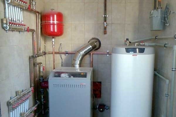
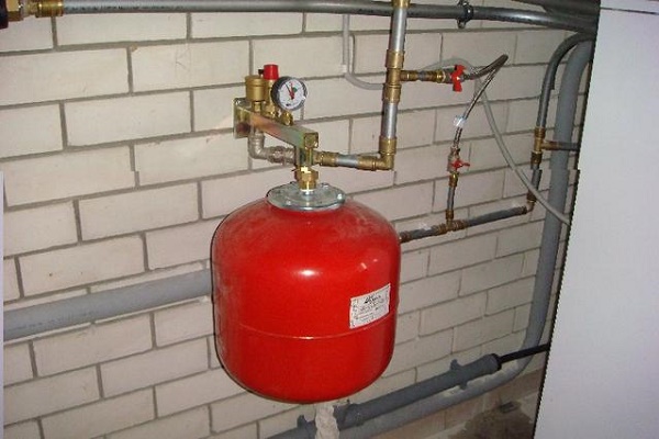
Thermal expansion in a closed system is compensated by the use of a membrane expansion tank, filled with water during heating. When cooling, water from the tank again goes into the system, thereby maintaining a constant pressure in the circuit.
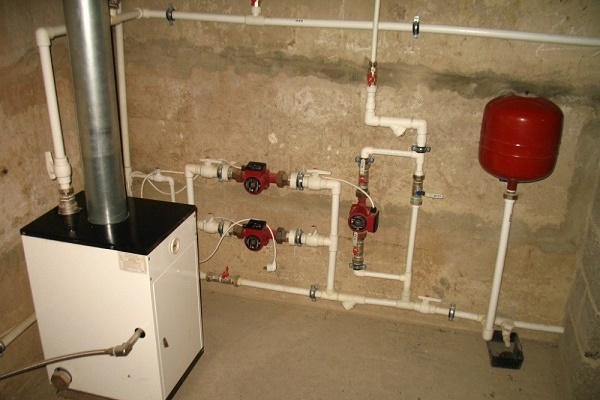
The pressure generated in the closed heating circuit during installation is transmitted to the entire system. The coolant is circulated forcibly, therefore this system is volatile. Without circulation pump there will be no movement of heated water through the pipes to the devices and back to the heat generator.
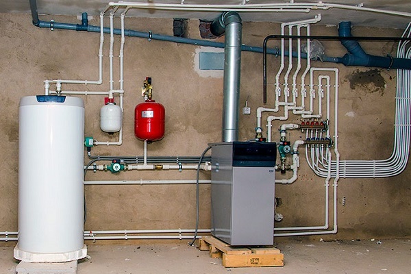
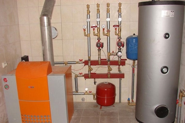
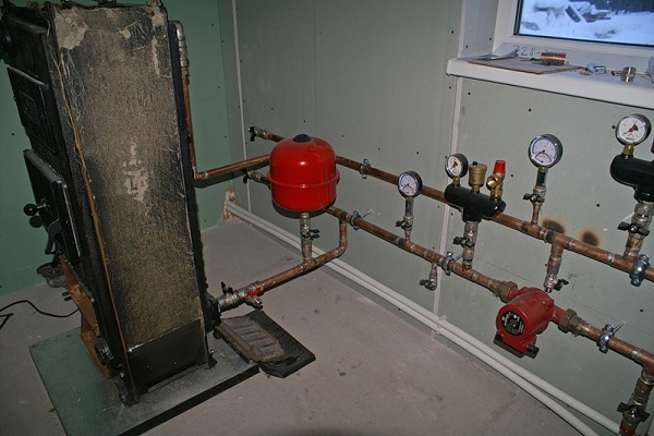
The main elements of a closed loop:
- boiler;
- air outlet valve;
- thermostatic valve;
- radiators;
- pipes;
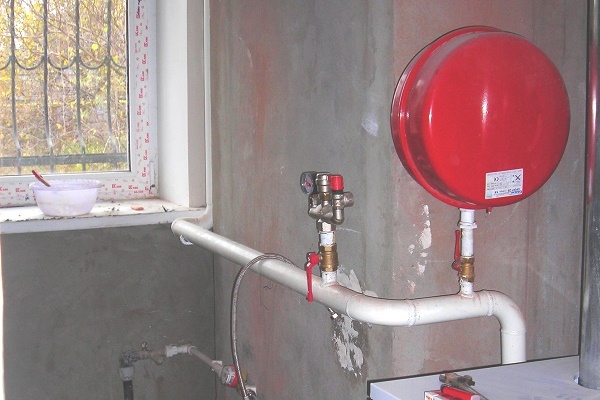
- expansion tank, not in contact with the atmosphere;
- balancing valve;
- ball valve;
- pump, filter;
- safety valve;
- pressure gauge;
- fittings, fasteners.
If the power supply at home is uninterrupted, then a closed system works efficiently. Often the design is supplemented by "warm floors", increasing its efficiency and heat dissipation.

This arrangement allows you not to adhere to a certain diameter of the pipeline, reduce the cost of acquiring materials and not place the pipeline at a slope, which simplifies installation. Liquid with low temperature must flow to the pump, otherwise its operation is impossible.

This option has one negative nuance - while with a constant slope, heating works even in the absence of power supply, then with a strictly horizontal position of the pipeline, a closed system does not work. This shortcoming is compensated by high efficiency and a number of positive aspects compared to other types of heating systems.
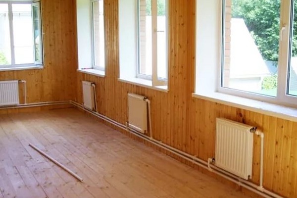
Installation is relatively simple and possible in a room of any size. The pipeline does not need to be insulated, heating occurs very quickly, if a thermostat is present in the circuit, then the temperature regime can be set. If the system is arranged correctly, then there are no losses of coolant, and therefore there are no reasons for replenishing it.
An undoubted advantage of the closed heating system is that the temperature difference between the supply and return allows to increase the operational life of the boiler. Closed circuit piping is less susceptible to corrosion. It is possible to upload to the circuit antifreeze instead of waterwhen the heating has to be turned off in the winter for a long time.

System protection against air
Theoretically, air should not enter a closed heating system, but in fact it is still there. Its accumulation is observed at a time when pipes and batteries are filled with water. The second reason may be the depressurization of the joints.
As a result of the appearance of air jams, the heat transfer of the system is reduced. To combat this phenomenon, special valves and taps for venting air are included in the system.

To minimize the likelihood of air jams, certain rules must be followed when filling a closed system:
- Supply water from the bottom to the top. To do this, lay pipes so that the water and air released move in the same direction.
- Leave the taps for venting in the open position and the taps for draining water in the closed position. Thus, with a gradual rise of the coolant, air will escape through open air vents.
- Close the vent valve as soon as water runs through it. The process continues smoothly until the circuit is completely filled with coolant.
- Start the pump.
If in the heating circuit aluminum radiators, then on each air vents are required. Aluminum, in contact with the coolant, provokes a chemical reaction, accompanied by the release of oxygen. Partially bimetallic radiators have the same problem, but much less air is formed.

In radiators, all 100% bimetal coolant is not in contact with aluminum, but professionals insist on the presence of an air vent in this case. The specific design of steel panel radiators is already equipped with valves for air release during the manufacturing process.
On old cast-iron radiators, air is removed using a ball valve, other devices are ineffective here.
The critical points in the heating circuit are the kinks of the pipes and the upper points of the system, so the air exhaust devices are mounted in these places. In a closed loop apply Mayevsky cranes or automatic float valves that allow air to be vented without human intervention.
In the case of this device there is a polypropylene float connected through a beam to the spool. As the float chamber fills with air, the float lowers, and when it reaches the lower position, it opens a valve through which air leaves.
In the volume freed from the gas, water enters, the float rushes up and closes the spool. To prevent debris from entering the latter, it is covered with a protective cap.

There are modifications where this process goes differently, but the principle is the same: the float in the lower position - gas is released; the float is up - the valve is closed, air is accumulating. The cycle repeats automatically and does not require the presence of a person.
Hydraulic calculation for a closed system
In order not to make a mistake with the selection of pipes for the diameter and power of the pump, a hydraulic calculation of the system is necessary.
Effective operation of the entire system is impossible without taking into account the main 4 points:
- Determining the amount of coolant that must be supplied to the heating devices in order to ensure the desired heat balance in the house, regardless of the outside temperature.
- Maximum reduction in operating costs.
- Decrease to a minimum of financial investments, depending on the chosen diameter of the pipeline.
- Stable and silent operation of the system.
Hydraulic calculation will help to solve these problems, which allows you to choose the optimal pipe diameters taking into account economically justified flow rates of the coolant, determine the hydraulic pressure loss in individual sections, link and balance the branches of the system.This is a complex and time-consuming, but necessary design stage.
Rules for calculating coolant flow
Calculations are possible if there is a heat engineering calculation and after selecting radiators for power. The heat engineering calculation should contain reasonable data on the volumes of thermal energy, loads, heat losses. If this data is not available, then the radiator power is taken over the area of the room, but the calculation results will be less accurate.

Start with the scheme. It is better to perform it in axonometric projection and apply all the known parameters. The coolant flow rate is determined by the formula:
G = 860q / ∆t kg / h,
where q is the power of the radiator kW, ∆t is the temperature difference between the return and supply lines. Having determined this value, the cross-section of the pipes is determined from the Shevelev tables.
To use these tables, the calculation result must be converted to liters per second according to the formula: GV = G / 3600ρ. Here GV denotes the flow rate of the coolant in l / s, ρ is the density of water equal to 0.983 kg / l at a temperature of 60 degrees C. From the tables, you can simply choose the cross section of the pipe without performing a complete calculation.

The sequence of calculation is easier to understand with the example of a simple scheme including a boiler and 10 radiators. The scheme must be divided into sections where the pipe cross section and the coolant flow rate are constant.
The first section is the line from the boiler to the first radiator. The second is the segment between the first and second radiator. The third and subsequent sections allocate similarly.
The temperature from the first to the last device gradually decreases. If in the first section the thermal energy is 10 kW, then when the first radiator passes, the coolant gives it a certain amount of heat and the waste heat decreases by 1 kW, etc.
You can calculate the coolant flow rate by the formula:
Q = (3.6xQuch) / (cx (tr-to))
Here, Quch is the heat load of the section, s is the specific heat of water, which has a constant value of 4.2 kJ / kg x s., Tr is the temperature of the hot heat carrier at the inlet, and to is the temperature of the cooled heat carrier at the outlet.
The optimum speed of movement of the hot fluid along the pipeline is from 0.2 to 0.7 m / s. At a lower value, air jams will appear in the system. This parameter is affected by the product material, roughness inside the pipe.
Both in open and in closed heating circuits use pipes made of black and stainless steel, copper, polypropylene, polyethylene of various modifications, polybutylene, etc.
At a coolant speed within the recommended range of 0.2-0.7 m / s, pressure losses from 45 to 280 Pa / m will be observed in the polymer pipeline, and from 48 to 480 Pa / m in steel pipes.
The inner diameter of the pipes in the section (dвн) is determined based on the heat flux and the temperature difference at the inlet and outlet (∆tco = 20 degrees C for a 2-pipe heating circuit) or the flow rate of the coolant. There is a special table for this:

To select a circuit, you should consider single and 2-pipe schemes separately. In the first case, the riser with the largest amount of equipment is calculated, and in the second, the loaded circuit. The length of the site is taken from the plan, executed on a scale.
An accurate hydraulic calculation can only be performed by a specialist in the appropriate profile. There are special programs that allow you to perform all calculations related to thermal and hydraulic characteristics that can be used when heating system design for your home.
Circulation pump selection
The purpose of the calculation is to obtain the pressure value that the pump must develop to drive water through the system. To do this, use the formula:
P = Rl + Z
Wherein:
- P is the pressure loss in the pipeline in Pa;
- R is the specific friction resistance in Pa / m;
- l is the length of the pipe in the design section in m;
- Z - pressure loss in the "narrow" areas in Pa.
These calculations are simplified by the same Shevelev tables, from which one can find the value of friction resistance, only 1000i will have to be calculated according to the specific length of the pipe. So, if the diameter of the inner pipe is 15 mm, the length of the section is 5 m, and 1000i = 28.8, then Rl = 28.8 x 5/1000 = 0.144 Bar. Having found the Rl values for each plot, they are summed.
The pressure loss value Z for both the boiler and radiators is in the passport. For other resistances, experts advise taking 20% of Rl, followed by summing the results for individual sections and multiplying by a factor of 1.3. The result is the desired pump head. For single and 2-pipe systems, the calculation is the same.

In the case when pump pick up according to the existing boiler, then apply the formula: Q = N / (t2-t1), where N is the power of the heating unit in W, t2 and t1 are the temperature of the coolant when leaving the boiler and on the return, respectively.
How to calculate the expansion tank?
The calculation is reduced to determining the amount by which the volume of the coolant will increase during its heating from the average room temperature + 20 degrees C to the working one - from 50 to 80 degrees. These calculations are not simple, but there is another way to solve the problem: professionals advise choosing a tank with a volume equal to 1/10 of the total amount of liquid in the system.

You can find out these data from equipment certificates, which indicate the capacity of the boiler’s water jacket and 1 radiator section. Then calculate the cross-sectional area of pipes of different diameters and multiply by the corresponding length.
The results are summarized, plus data from passports are added to them and 10% of the total is taken. If the entire system contains 200 liters of coolant, then an expansion tank of 20 liters is needed.
Tank Selection Criteria
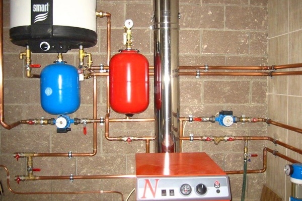
Make expansion tanks of steel. Inside is a membrane dividing the tank into 2 compartments. The first is filled with gas, and the second with coolant. When the temperature rises and water rushes from the system to the tank, then under its pressure the gas is compressed. The coolant cannot occupy the entire volume due to the presence of gas in the tank.
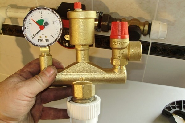
The capacity of the expansion tanks is different. This parameter is selected so that when the pressure in the system reaches its peak, the water does not rise above the set level. As a protection of the tank against overflow, a safety valve is included in the design.Normal tank filling is from 60 to 30%.

The choice of the optimal scheme
When heating in a private house, two types of schemes are used: single and 2-pipe. If you compare them, then the latter is more effective. Their main difference in the methods of connecting radiators to pipelines. In a two-pipe system, an indispensable element of the heating circuit is an individual riser, through which the cooled coolant is returned to the boiler.
Installation of a single-pipe system is simpler and less costly in financial terms. The closed loop of this system combines both the supply and return piping.
Single pipe heating system
In one and 2-story buildings with a small area, the closed-circuit single-pipe heating circuit has proven itself, representing a 1 pipe wiring and a series of radiators connected in series.
It is sometimes popularly called the "Leningrad". The coolant, returning heat to the radiator, returns to the supply pipe, and then passes through the next battery. The latest radiators receive less heat.

The advantage of such a scheme is called economical installation - it takes less time and material than for a 2-pipe system. In the event of failure of one radiator, the rest will work in normal mode when using bypass.
The possibilities of a one-pipe scheme are limited - it cannot be started in stages, the radiators warm up unevenly, so you need to add sections to the last in the chain. So that the coolant does not cool so quickly, it is necessary to increase the diameter of the pipes. It is recommended to connect no more than 5 radiators for each floor.
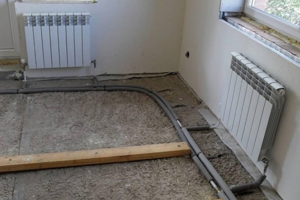
Two types of systems are known: horizontal and vertical. In a one-story building, a horizontal view of the heating system is laid both above and below the floor.It is recommended that the batteries be mounted at the same level, and the horizontal supply pipe is slightly sloping along the flow of the coolant.
With a vertical wiring, water from the boiler rises up the central riser, enters the pipeline, is distributed into individual risers, and of them - to the radiators. Cooling, the liquid down the same riser goes down, passing there through all the devices, it is in the return pipe, and from it the pump pumps it back to the boiler.

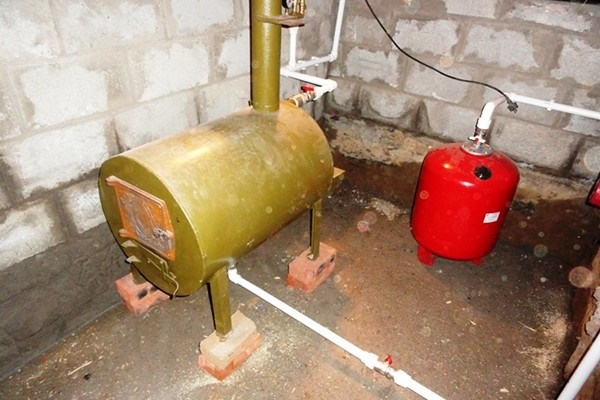
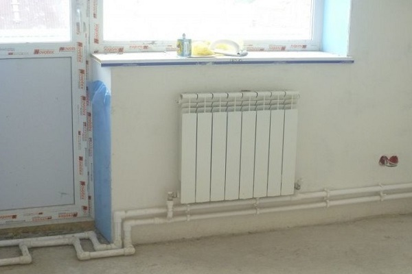
Selecting a closed type of heating system, installation is performed in the following sequence:
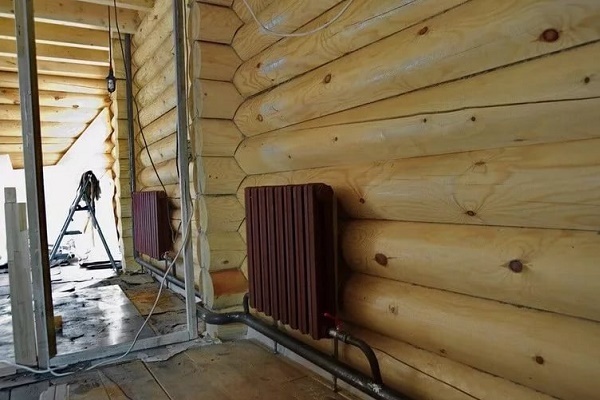
- Install the boiler. Most often, a place is allocated for him on the ground or first floor of the house.
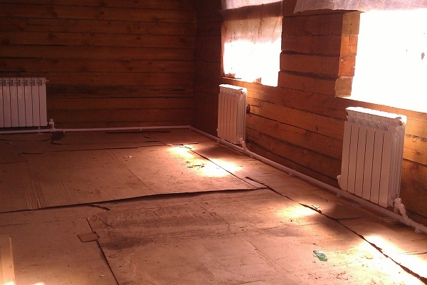
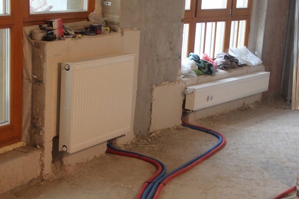
- Pipes are connected to the inlet and outlet pipes of the boiler, they are bred along the perimeter of all rooms. Connections are selected depending on the material of the main pipes.
- Install the expansion tank, placing it at the highest point. At the same time, a security group is mounted, connecting it to the highway through a tee. They fix the vertical main riser, connect it to the tank.
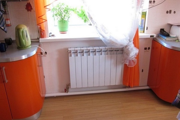
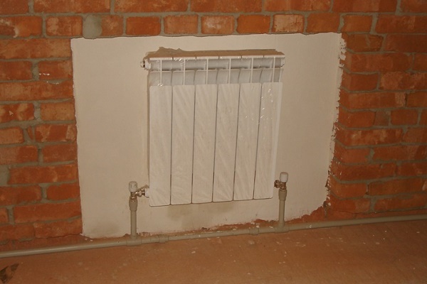
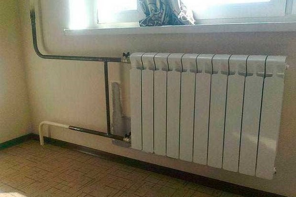
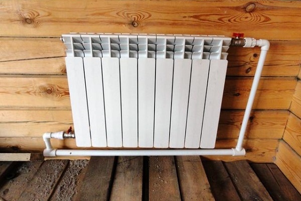
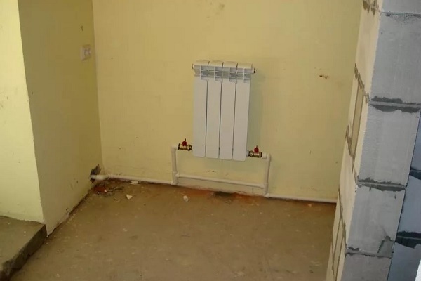
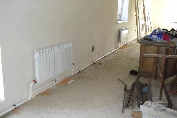
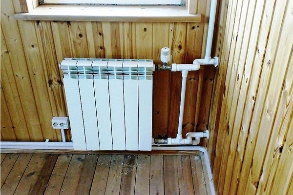
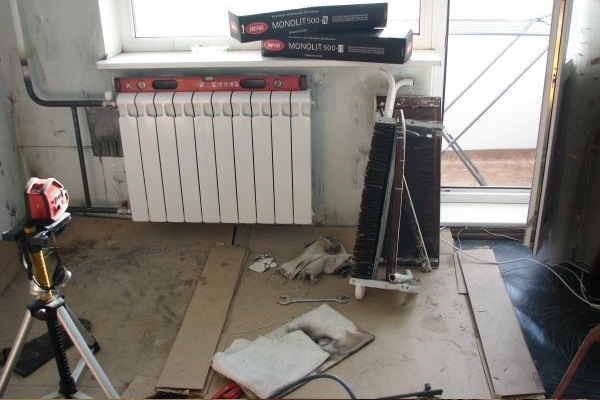
- Install radiators with the installation of Maevsky cranes. The best option: a bypass and 2 shut-off valves - one at the inlet, the other at the outlet.
- The pump is installed in the area where the cooled coolant enters the boiler, having previously installed a filter in front of the place of its installation. The rotor is placed horizontally.
Some masters install a pump with a bypass, so as not to drain the water from the system in case of repair or replacement of equipment.
After mounting all the elements, open the valve, fill the line with coolant, and remove air. They check that the air is so completely removed by unscrewing the screw located on the cover of the pump casing. If liquid escapes from under it, it means that the equipment can be started by previously tightening the previously unscrewed central screw.
With proven designs single pipe heating systems and device options you can find in another article on our site.
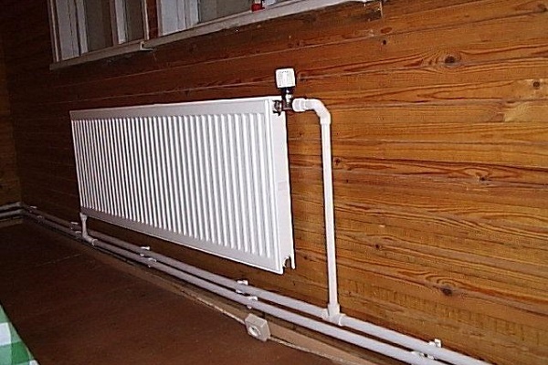
Two pipe heating system
As in the case of a single pipe system, there is a horizontal and vertical wiring, but there is both a supply and a return line. All radiators heat up the same. One type differs from another in that in the first case there is a single riser and all heating devices are connected to it.

The vertical diagram provides for the connection of radiators to a riser located vertically. Its advantage is that in a multi-storey building, each floor is individually connected to the riser.
A feature of the two-pipe scheme is the presence of pipes connected to each battery: one straight-through and the second reverse. There are 2 circuits for connecting heating appliances. One of them is collector, when 2 pipes fit from the collectors to the battery.
The scheme is characterized by complex installation, high material consumption, but in each room you can adjust the temperature.
The second is a parallel circuit is simpler. The risers are installed around the perimeter of the house, radiators are connected to them. A lounger runs across the floor and risers are connected to it.
The components of such a system are:
- boiler;
- safety valve;
- pressure gauge;
- automatic air vent;
- thermostatic valve;
- batteries
- pump;
- filter;
- balancing device;
- tank;
- valve.
Before proceeding with the installation, the issue of the type of energy carrier should be resolved. Next, install the boiler in a separate boiler room or in the basement. The main thing is that there should be good ventilation. Install the collector, if it is provided by the project and the pump. Adjusting and measuring equipment is mounted near the boiler.
A highway is brought to each future radiator, then the batteries themselves are installed. The radiators are hung on special brackets in such a way that 10-12 centimeters remain to the floor, and 2-5 cm from the walls. They supply instrument openings with shut-off and control devices at the inlet and outlet.

After installation of all nodes of the system, it is pressed. Professionals should be engaged in it because only they can issue the corresponding document.
Details features of the device of a two-pipe heating system described here, the article presents various schemes and gives their analysis.
Conclusions and useful video on the topic
This video shows an example of a detailed hydraulic calculation of a 2-pipe closed-type heating system for a 2-storey building in the VALTEC.PRG program:
Here it is described in detail about the device of a single-pipe heating system:
It is possible to install a closed version of the heating system yourself, but you can not do without expert advice. The key to success is a correctly completed project and quality materials.
Have questions about the specifics of the indoor heating circuit? Is there any information on the topic that is interesting to visitors to the site and to us? Please write comments in the block below.
 Open heating system: schematic diagrams and features of the arrangement
  One-pipe heating system Leningradka: schemes and organization principle
  Natural circulation heating system: common water circuit designs
  How are heating systems with pump circulation arranged: organization schemes
 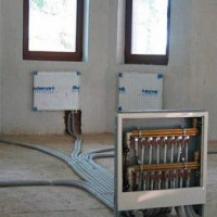 How the radial heating system works: schemes and wiring options
 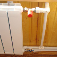 Two-pipe heating system of a private house: device diagrams + overview of the advantages
  How much does it cost to connect gas to a private house: the price of organizing gas supply
  The best washing machines with dryer: model rating and customer tips
  What is the color temperature of light and the nuances of choosing the temperature of the lamps to suit your needs
  Replacement of a geyser in an apartment: replacement paperwork + basic norms and requirements
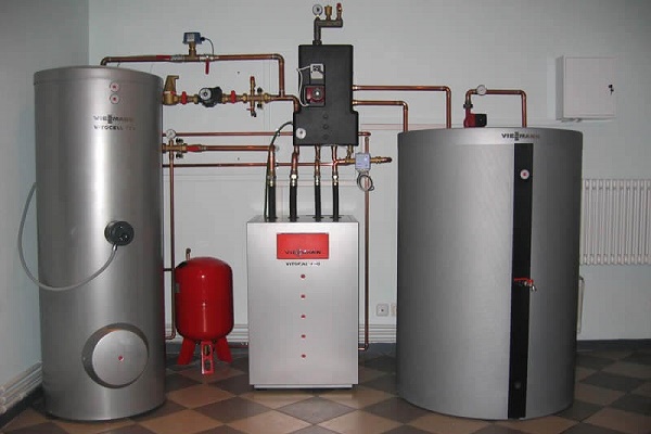
But not for every type of house it is suitable, it is also worth considering. The system, of course, is extremely effective, but try to install it in houses that are already “eleven” years old, and they are simply even planned for another heating network. It is worth considering that this option is suitable only for modern buildings in which even the very construction of the house was so originally conceived. Although I do not exclude that I could be mistaken, but in old houses I would not risk it.
In old houses there is no risk, but it is still advisable to redo the whole system, along with pipes and radiators. For example, when replacing the boiler. Actually, modern wall-mounted boilers all come with built-in pumps and expansion tanks. So, it remains only to change the pipes and preferably radiators. Better yet, install underfloor heating. The gain will be both in design and in efficiency.