Connection diagrams of the heating pump: installation options and step-by-step instruction
The even distribution of heat in a house with an autonomous heating system is due to the used model of the pumping device. Due to this equipment, forced movement of the warm medium through pipes and radiators is provided.
To determine which connection scheme for the heating pump will be optimal for independent implementation, many details have to be taken into account. In this article, we will consider in detail the possible connection schemes, we will analyze the connection rules in detail.
And also pay attention to the subtleties of choosing a place for installation, supplementing the material with thematic photos and diagrams.
The content of the article:
Pros and cons of using a heating pump
A couple of decades ago, in the private sector, houses were equipped with gravity-type heating. As a heat source, a wood stove or gas boiler was used. For overall circulation devices, there was only one area of application - district heating networks.
Today, manufacturers of heating equipment offer smaller units with the following advantages:
- The speed of movement of the thermal carrier has increased. The heat generated by the boiler quickly enters the radiators. Due to this, the process of heating the premises has significantly accelerated.
- The higher the speed, the higher the pipe throughput. This means that an identical amount of heat can be delivered to the rooms, with a trunk with a smaller diameter.
- Water heating schemes have undergone significant changes.. The highway can be laid with the slightest slope. Also, the complexity and length of the line can be anything. The basic rule is the rational choice of a heating pump based on the required power.
- With the help of a household circulating device, the organization of warm floors became possible in the house, as well as an efficient closed heating system.
- Now you can hide the entire heating communications linepassing through the rooms, which is not always successfully combined with the design of the room. Pipe laying options are quite common for suspended ceilings, in walls or under floor coverings.
The disadvantages of pumping systems include the conditionality of functioning from the supply of electricity and its consumption by the pumping device in the heating season.
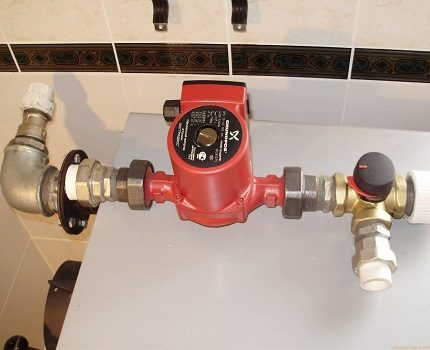
Therefore, if the site often loses power supply, it would be advisable to install a device to provide electricity in uninterrupted mode. The second drawback is not critical and can be fixed the right choice power and circulation pump models.
Choosing a place to insert the device into the system
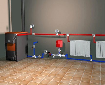
Installation of the circulation pump is supposed to be on the site immediately after the heat generator, not reaching the first branch line. The selected pipeline does not matter - it can be either a supply or a return line.
Where can I put the pump?
Modern models of household units for heating, made of high quality materials, withstand temperatures up to a maximum of 100 ° C. However, most systems are not designed for higher heating of the coolant.
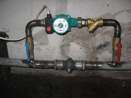
Its efficiency will be equally effective both on the supply and on the return branch.
And that's why:
- The density of water when heated to 50 ° C is 987 kg / m3and at 70 degrees - 977.9 kg / m3;
- The heating unit is capable of generating a hydrostatic pressure of 4-6 m water column and pumping nearly 1 ton of coolant per hour.
From this we can conclude: a negligible difference of 9 kg / m3 between the statistical pressure of the moving coolant and the return does not affect the quality of space heating.
Are there any exceptions to the rules?
As an exception, inexpensive solid fuel boilers - with direct type of combustion. Their device does not provide for automation, so at the time of overheating, the coolant begins to boil.
Problems begin to arise if the electric pump installed in the supply line starts to fill up with hot water and steam.
The thermal carrier enters through the housing with the impeller and the following occurs:
- Due to the action of gases on the impeller of the pumping device, the efficiency of the unit decreases. As a result, the velocity coefficient of the circulation of the thermal carrier is significantly reduced.
- An insufficient amount of cold liquid enters the expansion tank located near the suction pipe. The overheating of the mechanism increases and more steam is formed.
- A large amount of steam when it enters the impeller completely stops the movement of warm water along the line. Due to the increase in pressure, a trip occurs. fuse valve. Steam is emitted directly to the boiler room. An emergency situation is created.
- If firewood is not extinguished at this moment, the valve will not be able to cope with the load and an explosion will occur.
In practice, no more than 5 minutes pass from the initial moment of overheating to the actuation of the safety valve.If you install the circulation mechanism on the return branch, then the length of time for which the steam enters the device increases to 30 minutes. This gap will be enough to eliminate the heat supply.
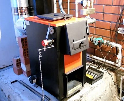
From this we can conclude that it is impractical and even dangerous to install a circulation device on the supply line. Pumps for solid fuel heat generators are best installed in the return pipe. However, this requirement does not apply to automated systems.
Heating with a group of separate highways
If the heating system is divided into two separate lines that heat the right and left sides of the cottage or several floors - it will be more practical to install an individual pump for each branch.
When installing a separate device for the heat line of the second floor, it becomes possible to save by adjusting the required operating mode. Due to the fact that heat has the property to rise, it will always be warmer on the second floor. This will reduce the rate of circulation of the coolant.
The pump is inserted in the same way - in the area immediately after the heat generator until the first branch in this heating circuit. Usually, when installing two units in a two-story house, the fuel consumption for servicing the top floor will be significantly less.
Schemes for different types of systems
Initially, it is necessary to determine the insertion zone of the circulation device. With its help, the process of active movement of the liquid is carried out - the flow passes through the boiler and is forcibly sent to the heating radiators.
For the location of the domestic pump, it is necessary to determine the most convenient area so that it can be easily maintained. On the pitch, it is set after safety block and shut-off valves of the boiler.
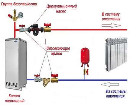
On the return pipe, the pump is placed after the expansion tank in front of the heat generator.
Due to the presence in the water of various mechanical impurities, for example, sand, problems may arise in the operation of the pumping mechanism. Particles contribute to jamming of the impeller, and in the worst case, to stop the motor. Therefore, directly in front of the unit, a strainer strainer must be installed.
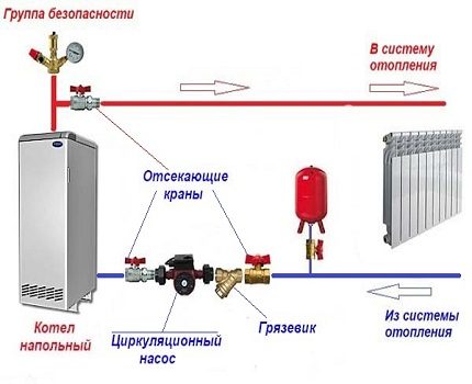
Separately, it is worth touching on the issue of an open heating system. It is able to work in two modes - with forced and gravity circulation of the coolant.
The second option is more suitable for areas with frequent blackouts. This is much more economical than the purchase of an uninterruptible power supply or generator. In this case, the unit with shut-off valves must be installed on bypass, and in a straight line to insert a crane.
In stores, you can find ready-made nodes with a bypass. In place of the flow valve, a check spring valve is located on them. This solution is not recommended - the valve produces a resistance force of 0.1 Bar, which is listed as a large indicator for a gravity-type circulation system.
It is better to use a flap valve instead. However, its installation is carried out strictly horizontally.
Solid fuel pump and boiler
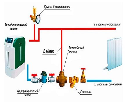
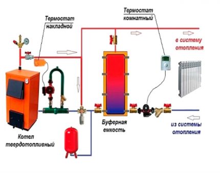
The pump is connected to the system with a solid fuel unit on the return line. In this case, the pumping device is connected to the boiler circuit with a bypass and a three-way mixing valve. In addition, the latter can be equipped with a servo drive and a surface temperature sensor.
Due to the fact that the maximum performance of heating equipment is used to its full extent only in the cold season, it is possible to install a heat accumulator (TA). It is able to absorb excess heat, and then, on demand, give it to the heating circuit.
This battery is made in the shape of a tank and lined with heat-insulating material. On one side of the device are two nozzles designed to connect it, and two on the other - to connect to the radiator line.
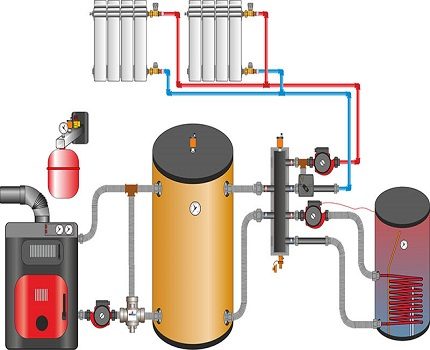
During the passage of fluid through the boiler, which operates at maximum, the coolant in the heat accumulator over time warms up to 90-110 degrees. In a large circuit, an insert of another circulation device is required.
Depending on the measure of cooling the liquid in the heating system, the amount of heat from the storage device will enter here through the valve.
Pump installation diagram
To perform its functions, household circulation equipment, regardless of the manufacturer, must be correctly installed on a pipe or shut-off and control valves.
Fastening is done using union nuts. This fixation option will allow you to remove it if necessary, for example, for inspection or repair.
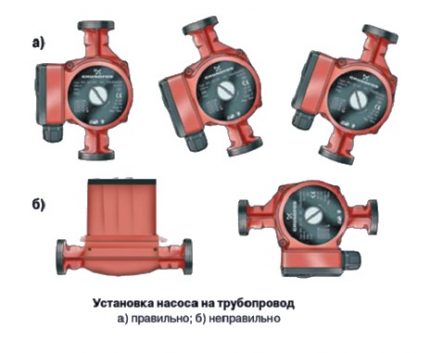
Correctly completed installation of all elements of the heating system ensures uniform heating of the entire line.
During the installation of the circulation pump, the following rules must be observed:
- It is allowed to install the device on any sections of the pipe. The pipeline may be horizontal, vertical or inclined. However, the rotor axis must be horizontal. Therefore, installation "head down" or, conversely, up - is impossible.
- It is worth paying attention to the location of the plastic box where the power contacts are located - they will be on top of the case. Otherwise, they may be flooded with water in an emergency. To do this, unscrew the mounting screws on the casing and turn it in the necessary direction.
- Observe flow direction. It is indicated by an arrow on the device body.
With all its weight, the pump presses on the body of ball valves located nearby. This should be taken into account when choosing fittings. High-quality parts are equipped with a powerful case, which during operation will not be cracked by daily stresses.
Installation of additional equipment
Regardless of the type of heating circuit used, where one boiler is the heat producer, it will be enough to install a single pumping device.
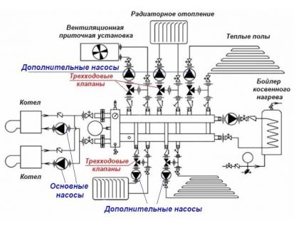
If the system is structurally more complex, it is possible to use additional devices that provide forced circulation of the liquid.
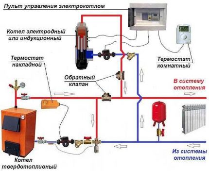
The need for this appears in the following cases:
- when heating a house, more than one boiler unit is involved;
- if a buffer capacity is present in the strapping scheme;
- the heating system diverges into several branches, for example, maintenance of an indirect boiler, several floors, etc .;
- when using a hydraulic separator;
- when the length of the pipeline is more than 80 meters;
- when organizing the movement of water in the floor heating circuits.
To carry out the correct piping of several boilers operating on different fuels, there is a need to install backup pumps.
For circuit with heat accumulator installation of an additional circulation pump is also required. In this case, the highway consists of two circuits - heating and boiler.
A more complex heating scheme is implemented in large houses on 2-3 floors. Due to the branching of the system into several highways, pumps for pumping the coolant involve 2 or more.
They are responsible for supplying coolant to each floor to various heating devices.
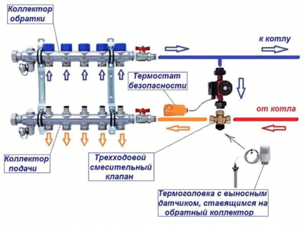
If it is planned to organize underfloor heating in the house, then it is advisable to install two circulation pumps.
In the complex, the pump and mixing unit is responsible for the preparation of the coolant, i.e., keeping the temperature at 30-40 ° C.
In some cases, the installation of pumping units is not required at all. Many models of wall-mounted electric and gas generators already have built-in circulation devices.
Rules for connecting to power
The circulation pump is powered by electricity. Connection is standard. It is recommended to conduct a separate power supply line with a voltage surge protector.
To connect, you need to prepare 3 wires - phase, neutral and ground.
You can choose any of the connection methods:
- through device differential automaton;
- network connection with uninterruptible power supply;
- pump power from the boiler automation system;
- adjustable by thermostat.
Many people wonder why complicate, because the connection of the pump can be done by connecting the plug to the wire. This is how the pumping device is plugged into a regular outlet.
However, experts do not recommend using this method because of the danger of unforeseen situations: there is no grounding and safety machine.
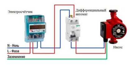
The first option is not complicated in self-assembly. It is necessary to set the differential machine to 8 A. The cross-section of the wire is selected based on the rating of the device.
In the standard scheme, the power supply is carried out to the upper sockets - they are marked with odd numbers, the load - to the lower (even numbers). Both phase and zero will be connected to the machine, so the connectors for the latter are denoted by the letter N.
To automate the process of stopping the circulation of the thermal medium when cooling to a certain temperature, an electrical circuit is used to connect the pump and thermostat. The second is mounted in the supply line.
At the moment when the temperature of the water decreases to the specified value, the device disconnects the electrical power circuit.
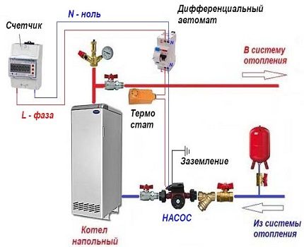
There is no difficulty in supplying electricity through an uninterruptible power supply, for this it has special connectors. They also connect a heat generator when there is a need to provide electricity.
If you choose the method of connecting the pump to the control panel of the boiler or automation, you will need good knowledge in the power supply system or the help of a professional.
Conclusions and useful video on the topic
Rules for installing heating equipment in the video:
The video explains the features of a two-pipe heating system and demonstrates different schemes for installing devices:
Features of connecting the heat accumulator to the heating system in the video:
If you know all the connection rules, there will be no difficulties with the installation of the circulation pump, as well as when connecting it to the power supply of the house.
The most difficult task is to insert a pumping device into a steel pipeline. However, using a set of handles to create threads on pipes, you can independently arrange the pump assembly.
Do you want to supplement the information presented in the article with recommendations from personal experience? Or maybe you saw inaccuracies or errors in the material reviewed? Please write about this in the comments section.
Or have you successfully installed the pump and want to share your success with other users? Tell us about it, add a photo of your pump - your experience will be useful to many readers.

 Selection of a circulation pump: device, types and rules for choosing a pump for heating
  Heating from an electric boiler: options for organizing heating based on an electric boiler
  Installation of a circulation pump: types, purpose and features of its installation
  Check valve for heating: action, types, pros and cons + installation diagram
  Heating systems in caravans: heater options for a comfortable temperature in the camper
  Thermal head for heating radiator: device, functioning + installation procedure
  How much does it cost to connect gas to a private house: the price of organizing gas supply
  The best washing machines with dryer: model rating and customer tips
  What is the color temperature of light and the nuances of choosing the temperature of the lamps to suit your needs
  Replacement of a geyser in an apartment: replacement paperwork + basic norms and requirements
We always have trouble with heating in winter, either the pipes were malfunctioning or just a poor supply, so we decided to invest in and install this pump. We put it in the bathroom instead of one of the batteries, this is not far from the outlet. The pipes became noticeably hot, at first the pump worked at the highest mode, but then set to medium. There isn’t a lot of electricity, the main thing is noiseless, but it’s forbidden to do this with us, and I don’t feel like living at 15 degrees.