Collector for heating: principle of operation, installation and connection rules

One of the effective options for modernization of the heating system, allowing to make it more productive and reliable, is the installation of a collector block. The device, which replaced the traditional constructions of the linear structure, is designed to increase the ease of use and maintainability of the system.
How the collector for heating functions and what installation features should be considered, we will consider in more detail.
The content of the article:
The principle of operation of the distributor
main destination distribution manifold - evenly distribute the heat flows coming from the main line along the system circuits and return the cooled liquid to the boiler due to the circulation circulation.
At the same time, individual branches of the system connected to the collector become independent of each other.
The device is an intermediate distribution unit, the key elements of which are two interconnected parts:
- feed comb - is responsible for the supply of coolant;
- reverse - performs the function of removing the cooled coolant to the heat generator.
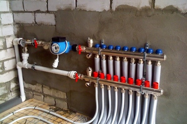
Together they form a collector group. Several leads depart from each comb for connecting circuits leading to heating appliances.
Each terminal of the device can be equipped with exhaust valves and a shut-off or control valve.
Their presence makes it possible to adjust the pressure inside each circuit and, if necessary, disconnect the branches for repair, for example, block the flow of coolant.
To increase system performance and to be able to control all heating processes in each room of a heated house, the building distribution comb They also use as a platform for installation:
- air exhaust valves;
- spillway valves;
- flow meters;
- heat meters.
The principle of the collector system is quite simple. The liquid preheated by the heat generator enters the feed comb.
Inside the intermediate assembly, the fluid velocity slows down due to the increased internal diameter of the device, it is redistributed between all outlets.

Knowing the flow rate of the coolant, equal to the power of the heat generator, and the speed of the water, it is easy to find the required cross-sectional area. Only previously should liters be transferred to a unit of mm convenient for calculations3.
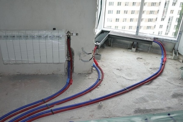
Through connecting pipes, the cross section of which is smaller than the diameter of the pipe of the collector assembly, the coolant enters the separately laid circuits and moves to the radiators or to floor heating.
Due to this distribution, each element is properly warmed up, supplied with a coolant of equal temperature.

Having reached the battery and giving up the heat obtained by heating, the liquid is directed through another pipe in the opposite direction to the distribution block. There she goes to the return comb, from where she is redirected to the heat generator.
For a country cottage manifold system It is considered to be the most effective and reliable.
The only thing that can stop a zealous owner is cost. After all, the arrangement of such a system will cost more than the device of a conventional tee-type system.

Types of collectors in heating systems
The collector systems used in the design of closed circulating heating systems come in three varieties.
Depending on the purpose of the structure, the market includes: radiator and solar systems, as well as devices equipped with a hydraulic arrow.
Type # 1 - radiator collector heating
Whatever type of heating is designed in the house, radiators are always present in it.Therefore, collectors that distribute coolant flows directly to the batteries installed in the rooms are the most popular type.

The collectors used in radiator heating, depending on the architectural and interior features of the room, can be connected in various ways.
By the method of connection, the radiator heating system can be performed in any of the following options execution:
- top connection;
- bottom accession;
- side installation;
- keeping diagonally.
The most common is still the lower connection method. With this layout, the contours hidden under the surface of the baseboard or floor are not so striking.
Yes, and calculations confirm that with the lower connection, all the advantages of private heating are fully manifested.
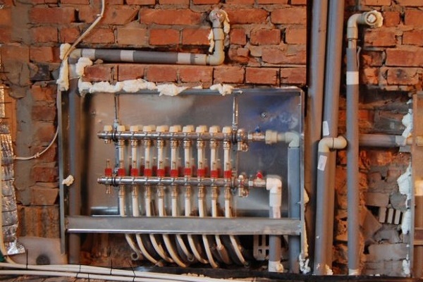
A collector for radiators is equipped on each floor of the house. They install it in the center, masking the device in a niche or in a cabinet specially designed for it on the wall.
The installation location should be chosen so that, as far as possible, branches of equal length are connected to all devices.
If it is impossible to achieve equality of the rings connected to the collector, then each branch is equipped with its own circulation pump.
In fact, all branches connected to the distribution node are an independent circuit with their own shutoff valves, and sometimes automation.
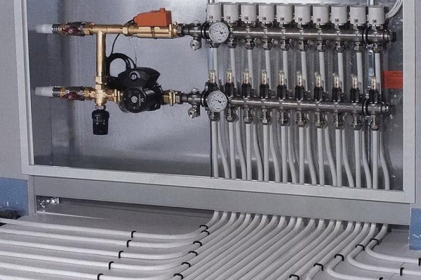
A striking example of a collector heating circuit are water heated floors.

Pipelines for underfloor heating are assembled from copper pipes or their plastic counterparts; one-piece fittings are used for connections.
Valves are mounted in the heating rings, with the help of which they regulate the coolant supply, and, if necessary, disconnect the "warm floors" from the common heating network.
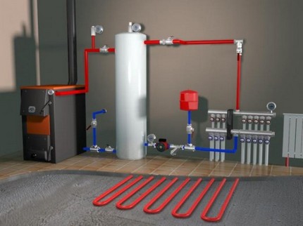
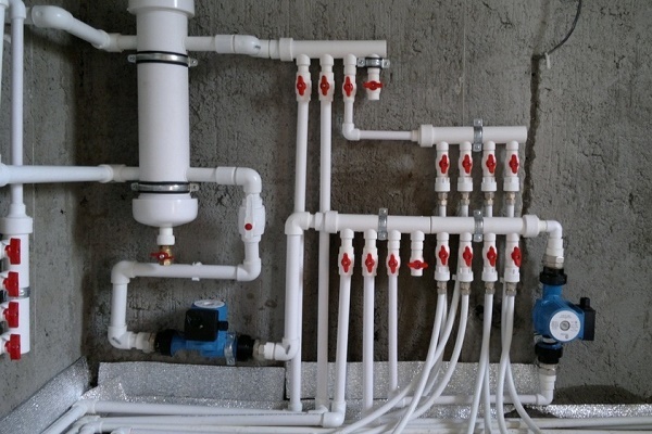
Such systems always equip circulation pump. It is placed in an intermediate manifold at the entrance to the pipe in the opposite direction.
The number of nozzles on the distribution unit depends on the number of rooms looped on one comb.
The number of collector groups is determined based on the length of the contours. The calculation is based on the ratio at which 120 meters of the pipeline are allocated to one collector group.
Type # 2 - hydraulic arrow
When equipping powerful and branched heating systems, which are designed in residential buildings with a large area, distribution manifolds equipped thermohydraulic dispenser or hydraulic arrow.
When installing the connecting link, on the one hand, a heating boiler circuit is connected to it, and on the other, radiator heating or “warm floors”.

The presence of a hydraulic distribution arrow allows solving several problems at once:
- to avoid sudden temperature changes in the pipes, detrimental to the operational life of the system;
- due to mixing and secondary circulation of a part of the heat carrier, to maintain a constant volume of boiler water, as well as save fuel and electricity;
- if necessary, compensate for the flow deficit in the secondary circuit.
Maintaining the temperature balance is achieved due to the fact that the device allows you to separate the hydraulic circuit of the boiler from the secondary circuit.

Optimum operation of a system equipped with a hydraulic boom can be ensured provided that each circuit is equipped with its own circulation pump.
Type # 3 - Solar Collector Installations
Devices of this type are chosen when arranging an autonomous water supply in non-gasified areas where the level of solar radiation is quite high.

The design of solar installations is slightly different from traditional analogues. In fact, they are a kind of greenhouses that accumulate solar energy.
The natural circulation of the coolant in them is due to convection flows and under the action of fans attached to the absorbing plate.
The sun-absorbing distributor is a small flat box covered with a black absorbent plate. This heat-absorbing plate also accumulates heat.
The accumulated heat is transferred to the coolant, in the role of which air or liquid circulating through the pipes can act.

On sale you can come across mobile solar collector systems. Their design is designed so that mirrors and heating elements “monitor” the movement of the sun, so that its energy is absorbed to the maximum.
But due to the high cost of equipment application of solar installations as the main source of heating in the climate, even the southern regions of our country are unprofitable.
And therefore, they are more involved as an additional source of heat in the arrangement of heating systems using solid fuel and gas boilers.
Distribution Combs Modifications
Today on the equipment market there are many varieties of collectors for heating systems.
Manufacturers offer both connecting links of the simplest design, the design of which does not provide for the availability of auxiliary fittings for regulating equipment, as well as manifold blocks with a full set of mounted elements.

Simple devices are brass models with an inch passage of branches equipped with two connecting holes on the sides.
Such devices have plugs on the return manifold, instead of which additional devices can always be installed in case of “building up" the system.
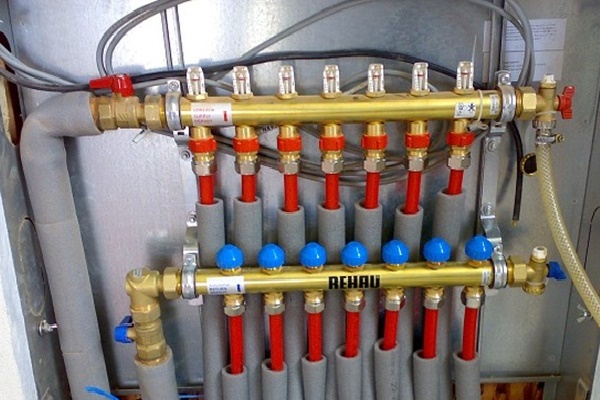
Intermediate prefabricated units more complex in design are equipped with ball valves. Under each branch, they provide for the installation of stop valves. The expensive expensive models can be equipped with:
- flow meterswhose main purpose is to regulate the flow of coolant in each loop;
- temperature sensorsdesigned to control the temperature of each heater;
- air vent valves automatic type for water discharge;
- electronic valves and mixersaimed at maintaining the programmed temperature.
The number of circuits depending on the connected consumers can vary from 2 to 10 pieces.

If we take the material of manufacture as a basis, then intermediate prefabricated collectors are:
- Brass - differ in high operational parameters at an affordable price.
- Stainless - Steel structures are extremely durable. They can easily withstand high pressure.
- Polypropylene - Models made of polymer materials, although they are not very expensive, are inferior to metal "brothers" in all characteristics.
Models made of metal are treated with anticorrosive compounds and extended with thermal insulation to extend the service life and increase operational parameters.

Parts of the device can be molded or equipped with collet clamps, allowing connection with metal-plastic pipes.
But experts do not advise choosing combs with collet clamps, since they often “sin” by leaking coolant at the junction of the valve. This is due to the rapid failure of the seal. And replacing it is not always possible.

Good Choices
The main difficulty lies not only in the installation of the collector, but also in the correct choice of equipment.
When choosing a comb model, one should be guided by the following parameters:
- Maximum allowable pressure for this model. It determines the type of material from which the valve can be made.
- Bandwidth of the node.
- The presence of auxiliary devices.
- The number of outlet nozzles of the comb. It must match the number of cooling circuits.
- Possibility of additional connection of elements.
All operational parameters are indicated in the passport to the product.
To equip floor-independent heating circuits equipped with autonomous control, combs must be mounted on each floor of the house.
When choosing and installing floor distributors, they are guided by the parameters of the "subsystem" that they are designed to serve.

This greatly simplifies the maintenance of the heating system and its repair.
Since the collector block is an expensive pleasure, in order to protect yourself from disappointments when the system quickly exits the system, when choosing a model, it is worth focusing on the products of trusted manufacturers.
You can safely trust such manufacturers as GREENoneTEC, "Rehau", "Soletrol", "Oventrop" and "Meibes". In each series of leading European manufacturers, you can pick up a complete set of necessary additional equipment.
Auxiliary elements and fittings to the collector block must also comply with GOST and TU.

Each of the additional structural elements performs its function:
- automatic air vent - mounted if the unit and radiators are located on the same floor;
- adapter - required when installing an air vent with a diameter of ½ inch, provided that the manifold thread is ¾ inch.
- a corner - allows connecting pipes and directing the air vent upwards.
- crane - necessary for connecting to the device a pipe coming from the boiler;
- drivingequipped with a cap nut - will allow, if necessary, to shut off the coolant supply and, having unscrewed the cap nut, disconnect the device.
If you plan to connect from the collector water floor heating, In addition, you need to install a tap for recharge.
To fix the collector to the wall, clamps “planted” on plastic dowels will also be required. When mounting the structure, it is also permissible to use special brackets.
Such designs are convenient in that the upper collector is pushed forward, so that the unit pipes do not interfere with the supply of the pipeline to the lower collector.
Installation and Connection Rules
It is best to choose and install a collector at the design and installation stage of the heating system.
Install such intermediate structures in rooms protected from excessive moisture. Most often, for these purposes, a place is allocated in the corridor, pantry or dressing room.

On sale there are overhead and built-in models of metal cabinets. Each model is equipped with a door and stamping on the sides.
In the absence of the ability to install a metal cabinet, they do it easier by fixing the device directly to the wall. A niche for the arrangement of the collector block is placed at a low height relative to the floor.
There is essentially no generally accepted installation instruction for manifold distribution circuits. But there are a number of key points regarding which experts have come to a common denominator:
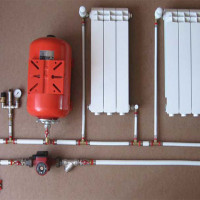
- The presence of an expansion tank. The volume of the structural element must be at least 10% of the total amount of water in the system.
- Availability of a circulation pump for each installed circuit. Regarding this element, not all experts are unanimous. But still, if you plan to use several independent circuits, for each of them it is worth installing a separate unit.
In front of the circulation pump on the return flow line place expansion tank. Due to this, it becomes less vulnerable to the turbulence of water flows, often occurring in this place.
If a hydraulic arrow is used, the tank is mounted in front of the main pump, the main task of which is to provide circulation on a small circuit.
The location of the circulation pump is not critical. But, as practice shows, the resource of the device is slightly higher precisely on the "return".
The main thing during installation is to position the shaft horizontally. If this condition is not met, the first bubble of accumulated air will leave the unit without cooling and lubrication.
The process of assembly and connection of the collector system is clearly presented in the video block.
Conclusions and useful video on the topic
Video guide for sequential assembly of the manifold block:
Video review of the installation and operation of a modular plastic collector:
Distribution unit for “warm floor”:
Properly selected and installed collector wiring guarantees the efficiency and reliability of the heating system.
Due to the small number of joints and tees, the likelihood of leaks of such structures is minimized. Well, the ability to adjust the heating temperature of each heating radiator makes the operation of the heating system particularly comfortable.
If you have the necessary knowledge or have experience connecting a collector heating system, please share it with our readers. You can do this by leaving a comment at the bottom of the article.
 Expansion tank for closed heating: operating principle and device + how to choose and install in the system
  Heating elements for heating: types, principle of operation, rules for the selection of equipment
 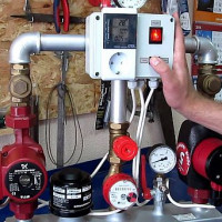 Water pump for heating: types, specifications and selection rules
 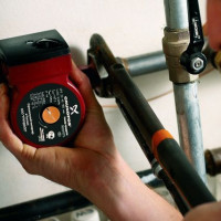 How to calculate a pump for heating: calculation examples and equipment selection rules
 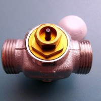 Three-way valve on the heating system: operation, selection rules, diagram and installation
 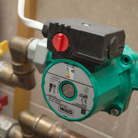 Connection diagrams of the heating pump: installation options and step-by-step instruction
  How much does it cost to connect gas to a private house: the price of organizing gas supply
  The best washing machines with dryer: model rating and customer tips
  What is the color temperature of light and the nuances of choosing the temperature of the lamps to suit your needs
  Replacement of a geyser in an apartment: replacement paperwork + basic norms and requirements
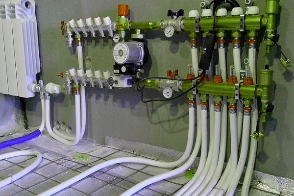
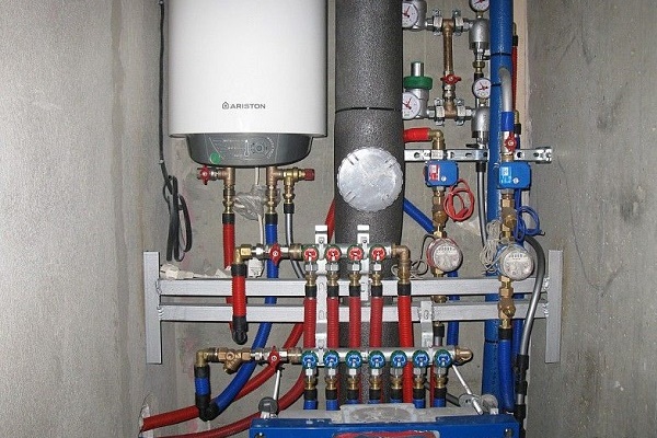
In our apartment, a plumber installed such a brass collector for four branches. We did parallel piping when installing a water heater in case there was no central hot water supply. For fifteen years, no leaks. At first, they only got confused for a long time about which pipe goes to which device, and you need to hang up labels with names immediately when mounting on branches.
3 years ago, we had a floor made and a stainless distribution manifold from Elite Metal was installed. So far, too, the flight is normal.