Grounding a gas boiler in a private house: standards, features of the device and checks

The installation of thermal equipment operating on natural gas is a widespread practice both in industry and in everyday life. But domestic installations are significantly inferior in power and other technical parameters. At first glance, a home gas water heater (boiler) is a simple equipment that presents a minimum of requirements to a potential owner, right?
Then why is the grounding of a gas boiler in a private house a mandatory norm and can it be ignored? We will help you understand - in this publication, the reasons for grounding, the features of its implementation, the norms and rules of verification are considered. Also shown are device diagrams, visual photos and video recommendations.
The content of the article:
Why do you need to ground the gas boiler?
Modern gas boilers traditionally contain control elements based on the principle of high-tech digital electronics.
Schemes of such equipment contain:
- digital microcontrollers;
- sensitive electronic sensors
- field effect transistors and planar microcircuits.
For electronics of this design, the presence of static electricity is "like death." At the most unexpected moment, a gas boiler may cease to function due to failure of electronic components from exposure to static microcurrents.
This is one of the main reasons requiring a mandatory grounding circuit in gas boiler circuit.

Another equally significant reason for the introduction of grounding is a clear danger of uncontrolled gas ignitionwhat creates high risks of fire or explosion of a gas boiler.Here, again, the notorious static electricity plays its "negative" role, and only the correct arrangement of the grounding circuit will help to get rid of it. The rules for the safe use of a gas boiler are discussed in next article.
Norms and rules of grounding
Regulatory requirements and rules describing the grounding circuit of the gas column are presented in an official document PUE.
According to the established standards for grounding a domestic gas boiler in the house, the equipment must be supplemented with an earth circuit, however, it does not indicate specifically which circuit should be used - industrial or home-made.

Meanwhile, regardless of the method of manufacturing the contour grounding system, it is rather specific to the PES document Section 1.7.103 contour loop resistance parameters are specified.
For a system built at home or using a team of specialists, the following requirements are relevant: “The total resistance to spreading of grounding conductors ... of all repeated grounding ... at any time of the year should be no more than 5, 10 and 20 Ohms, respectively, at line voltages of 660, 380 and 220 A three-phase current source (380, 220 and 127 V for a single-phase current source). In this case, the resistance to spreading of the ground electrode of each of the repeated grounding should be no more than 15, 30 and 60 Ohms, respectively, at the same voltages.
In practice, representatives of the gas service require that the resistance does not exceed 10 ohms.
According to the regulations of the PES document, it is categorically unacceptable to use the following elements for grounding for a domestic gas boiler:
- land lines of stationary household outlets;
- surfaces of heating pipelines;
- surface pipes of sewer networks;
- pipes of stationary gas lines and other pipelines of flammable or explosive liquids, gases, mixtures.
It is allowed to use metal water pipes laid in the ground, reinforced concrete foundations with reliable waterproofing, metal structures of structures located in the ground, etc. (as a natural grounding conductor) (Section 1.7.109 PUE).
If there is nothing suitable for the role of an earthing switch nearby, it is mandatory to equip an individual grounding circuit.
Arrangement of the grounding loop of the gas column
So, in case you still doubt whether it is necessary to ground a household gas boiler in a residential building, the answer is unequivocal - necessary. And immediately upon the installation of new gas equipment with subsequent verification of the correctness of the device "ground".
Therefore, it is worth considering the traditional device diagram, materials and components required for the organization of "contour ground", as well as the features of the verification.

The circuit diagram, as a rule, is the classic version of the mold The "triangle"immersed in soil to a depth of not less than 0.5 meters. In this case, the metal points (preferably coated with a layer of copper) are the corner points of the “triangle”.
The optimum immersion depth of the metal electrode pins is 4.5 meters. The connecting material between the electrode elements is a metal strip.
Thus, the construction of the contour of the "Earth triangle" covers the process of driving three metal pins-electrodes into the ground, followed by the manufacture of a loading trench between them, where a metal strip is laid and welded to the pins-electrodes.
According to the same rules of the PUE, the “triangle” of grounding should be installed at least 1 meter from the wall of a residential building. The classic distance between the elements of the contour electrodes driven into the ground is 2.5 meters.
However, instead of the “triangle” option, it is also quite suitable (PES is not prohibited) just a straight metal strip between two electrodes immersed in soil, the length of which is at least 3 meters (the circuit solution is shown below). The dimensions of grounding conductors and grounding conductors laid in the ground are also indicated in PUE table 1.7.4.


Separately, it is worth noting the technology of immersion of metal pins-electrodes in the ground, given the immersion depth of 4.5 meters.
In order to immerse a relatively thin in diameter metal pin electrode, several short segments are used that are connected to each other as they are immersed. Connections are made using special couplings or by welding. (the second option is preferable).
We recommend that you familiarize yourself with detailed guidance by choosing the right material and arranging grounding with your own hands.
How to connect the ground loop to the shield?
The fabricated and installed contour element for a domestic gas boiler must be correctly connected to the gas equipment switching unit (usually a three-pin mains socket or control panel).
PES standards allow the use of different types of conductors as a communication line, but stipulates the diameter of the wire depending on the material of the wire used: copper, aluminum, steel.

Allowed as part of the power switching equipment of a gas boiler install an RCD (residual current device), but only strictly in the presence of a contour grounding system. It is also allowed to apply RCD sockets. This point is marked by the rules of PES.
Features of checking the grounding of gas equipment
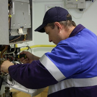
In a situation where the representative of the gas service checks the correct installation of the boiler, its connection and operation, the question of checking the correct grounding of the home gas boiler is not worth it. However, in practice, a kind of technical incident often happens.
Indeed, the electrical grounding circuit, in fact, is seen as the prerogative of representatives of the service responsible for power supply. This means that the circuit check is carried out by the electrical service, which is also confirmed by the rules of the EMP.

To perform the check, special electrical equipment (laboratory) is required. By means of an electrical measuring laboratory, not only the current spreading resistance in the circuit is measured, but also the degree of lightning protection.
However, this option is usually applicable to industrial equipment. For the domestic sphere, as practice shows, a lot in terms of verification depends on the local rules of each individual region.
Federal legislation specifically specifies only the standards for periodic inspections (PTEEP Appendix 3, p. 26), and also stipulates the rules for the preparation of equipment and commissioning (PTEEP, PUE).
According to the regulations, it is required to check the boiler grounding at least once a year. Based on the results of the audit, the owner of the gas equipment is issued a relevant document (ACT on the inspection). Methods of measuring grounding resistance we examined in this stuff.
Conclusions and useful video on the topic
The video below shows the sequence in which the event to create protection for gas equipment is carried out.
Thanks to the video, you can get a complete picture of the necessary work, the tool used and other subtleties of the process:
It is possible and necessary to supplement a household boiler with a grounding component, as practice shows. Even if the production of such work requires a financial cost from a potential user, it is worth it.
Equipping the geyser with an earthing circuit, the user of the equipment not only repeatedly increases the reliability of the equipment, but also provides a high level of personal safety.
Do you want to supplement the above material with useful comments? Or you still have questions about grounding? Feel free to ask for advice from our experts and other visitors to the site, write your comments - the feedback form is located below the article.
 Replacing a gas boiler in a private house: norms and rules for completing the procedure for replacing gas equipment
 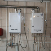 What determines the life of a gas boiler in a private house: what affects + life extension tips
  Gas boiler draft sensor: how it works and works + subtleties of functionality testing
 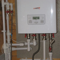 Connecting a double-circuit gas boiler to the heating system: requirements and norms + installation steps
  The principle of operation of a dual-circuit gas heating boiler and features of its connection
 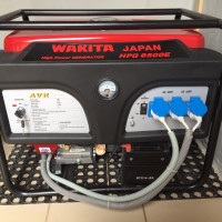 Gas generator for a gas boiler: specifics of choice and features of connection
  How much does it cost to connect gas to a private house: the price of organizing gas supply
  The best washing machines with dryer: model rating and customer tips
  What is the color temperature of light and the nuances of choosing the temperature of the lamps to suit your needs
  Replacement of a geyser in an apartment: replacement paperwork + basic norms and requirements