Gas boiler draft sensor: how it works and works + subtleties of functionality testing

Modern gas equipment, as a rule, can work fully automated. Thanks to the built-in components for monitoring the safe operation of equipment, the reliability of the system as a whole is ensured. One of these devices is a gas boiler draft sensor.
Agree that using equipment that does not require the constant presence of a person is quite convenient. But by what principle does the traction sensor work and is it so reliable?
We will consider these issues in our publication - we will talk about the device of the traction sensor, its functionality and features of the performance test. Supplemented material supplemented by thematic photos and video materials.
The content of the article:
Design and principle of operation of the sensor
Given the variety of gas boilers, it should be noted that traction control sensors are also of different designs. If we consider their design exclusively generalized, we will talk about a fairly simple mechanism of devices.
The basis of almost any sensor for controlling the draft of a gas boiler is a bimetallic element that changes shape when the temperature background changes. In fact, this is a simple bimetallic plate that bends when heated or cooled.
A change in the shape of the plate is controlled by a contact group that transfers the state of the contacts to “On” or "turned off". The switching signal of the contact group is transmitted to the gas boiler controller or to a simpler gas supply control mechanism.
The type of sensor that monitors draft in the smoke channel depends on the boiler used.
So, there are two types of gas boilers that exist and are applied in practice:
- Structures equipped with a simple chimney (with natural draft).
- Structures equipped with a chimney with a turbine (with forced draft).
These designs are different from one another and the thrust sensors used for them also vary.
Devices for boilers with natural draft
In natural draft boilers, a so-called flue gas hood is used, a simple miniature thermostat is built into the body, as shown in the picture below.
A miniature thermostat of simple design is usually endowed with the appropriate temperature label directly on the body (on the metal shell). This label (e.g. 75º) indicates contact temperature response sensor.

Such a device operates simply. If the flue gases passing through the hood with the sensor installed heat the device above the set temperature parameter (which indicates a violation of the draft mode), the contacts are open.
Accordingly, due to an open circuit, the gas supply system to the boiler will be turned off (blocked). The equipment will restart only after the sensor cools down and the open contact is restored.
Turbine boiler sensor designs
Boilers equipped with a chimney with a turbine have a slightly different sensor for determining the draft of a gas boiler with a functional principle that differs functionally. First of all, the difference lies in the fact that the sensor actually controls the fan of the boiler turbine. In other words, the optimal flue gas draft is controlled by a fan.
That is why the device for draft sensors of turbine gas boilers is made not under temperature control, but under control of the volume of passing carbon monoxide.
Such sensors work on the fact of the presence of optimal vacuum inside the combustion chamber, have a contact group of three elements:
- contact COM;
- normally open (NO);
- normally closed (NC).
Structurally, the devices are made different in form, but their principle of action remains unchanged. Upon the formation of operating conditions inside the chamber of the gas boiler (optimal vacuum), the contact group closes by the supplied air pressure, sending a signal to the gas supply.

How to check the functionality of the sensor?
Violations of traction of a gas boiler are often made to be compared precisely with sensors. In any case, many masters traditionally indicate a malfunction of the traction sensor.
Checking how the draft detection sensor works on a domestic gas boiler is quite simple. It should be noted that periodically checking such structural components is, in fact, commonplace. Especially for boilers equipped with a fan.
Stage # 1 - Performing Verification of the Control Sensors
Almost every equipment with a fan has special test points, using which the sensor is tested.
Test points (fittings) are usually located in chimney areas (top of the boiler). An example of the location of such elements is shown in the picture below. Both fittings are marked accordingly. That is - they have the designations "+" and "-" indicating the flow path.
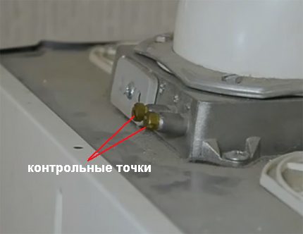
Next to the control fittings, there is usually another control interface (left, closed by a lid), through which it is permissible to measure the temperature of the gases and the efficiency of the equipment.
The measurement procedure is as follows:
- Twist the protective caps on the fittings.
- Connect the pressure gauge tubes to the fittings.
- Observe the accuracy of the connection at the points "+" and "-".
- Switch on the “Chimney sweep” mode on the boiler.
- Wait for the output of the equipment to the maximum.
After the equipment reaches maximum power, check the pressure gauge. The device should show permissible vacuum levelnot exceeding the established range for a particular brand of gas boiler. The required range can be found in the documentation for the equipment.

The procedure that demonstrates how to check the draft sensor on a household gas column, in addition to measuring with a manometer, also includes another necessary action - checking the boiler pressure switch.
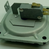
The gas boiler fan is traditionally equipped with a device called a pressure switch. Thanks to this device, it is carried out fan control and burner control gas boiler.
The pressure switch is connected to the air duct by rubber tubes. However, to check this element of the circuit, it is necessary to open the body of the gas boiler.

The principle of operation of this technical pair is quite simple. From the air channel through the rubber tube, pressure (negative relative to the pressure in the second tube) is taken by a pressure switch.
If the pressure selection is normal, the contact circuit of the pressure switch is closed - the gas boiler is functioning normally. In case of a change (deviation) in the vacuum level, the pressure difference changes, which leads to a rupture of the contact group of the pressure switch. Accordingly, the equipment is taken out of operation (boiler lockout).

Any proprietary pressure switch always has a designation of operating parameters on the body part. In particular, the parameter of the response pressure of the device to turn on and off is indicated (for example, at the pressostat shown in the photo above, this is 70/45 Pa). In other words: in this case, the gas burner operates at a pressure of 70 Pa and is blocked at a pressure of 45 Pa.
Stage # 2 - checking the boiler pressostat
In order to check the pressure switch, you need to perform a simple action - to determine the quality of switching the electrical circuit of the device. The switching element of the pressure switch is a conventional micro switchbuilt into the design of the device.
The microswitch is controlled (contacts close or open) by a plate, which is influenced by the pressure of the air entering the device through the tubes.
The contacts of the microswitch are displayed on the outside of the device. Accordingly, to check, you need to connect to the contact group a measuring device (multimeter) configured to measure the ohm resistance.
Each branded device is equipped with an electrical circuit indicated on the housing. In accordance with this scheme, the probes of the multimeter and the contacts of the device are connected.

After connecting the probes of the multimeter, a piece of silicone tube is connected to the negative pressure channel of the pressostat. Through the connected tube on the device, negative pressure is created (simply by sucking air in through the mouth) and at the same time the multimeter readings are monitored.
During normal switching, the arrow of the device will show the minimum resistance or will not react at all depending on the pressure created in the tube.If the microswitch is faulty (the switching channel is broken), the multimeter will not show any reaction. In this case, the pressure switch must be replaced with a new one.
We recommend that you familiarize yourself with the intricacies of the inspection and gas boiler service.
Stage # 3 - Identifying the Reason for Traction Reduction
Not always the reason for the decrease in traction is a breakdown of the sensor.
So, practice demonstrates that insufficient traction can be due to many other factors:
- clogged air transfer tubes;
- clogging of the inner area of the fan snail;
- condensation inside silicone tubes;
- foreign objects entering the tubes.
One of the common causes of a decrease in boiler draft is often clogging the internal area of the fan coil. Cleaning this area restores traction in full.

On the blades of the fan impeller and the walls of the cochlea after prolonged operation of the gas boiler, a large amount of dust and burning is collected. Over time, these deposits condense, acquire a rigid structure and, as a result, create significant resistance to air flow. This is one of the common causes of boiler loss of traction.
The boiler fan, of course, will have to be dismantled before cleaning the inside. Most boiler designs provide for easy disassembly / installation of the fan. Usually, it is enough to unscrew two or three fixing screws to disconnect the component from the chassis. First, disconnect the gas boiler from the power supply.

Water flushing should be carried out in such a way that moisture does not get on the stator winding of the electric motor and other electrical elements. The best option seems to be cleaning by blowing the inner area of the cochlea and blades with compressed air. True, at home, this option is often impossible.
Recommendations for cleaning and servicing the geyser we gave in next article.
Stage # 4 - Traction Retest
Upon completion of the cleaning procedure for the gas boiler turbine fan and installation of this component in its workplace, it is necessary to repeat the testing of the equipment for the flue gas draft level.
That is, again, the operation described above should be performed - checking the vacuum level inside the combustion chamber. The previously disassembled body of the gas boiler must be put in place - bring the boiler into full working condition.

As a rule, the test results show a slight increase in the pressure gauge, which indicates the normal working condition of the flue gas duct. Given this practice, it can be concluded that the temperature sensor or pressure switch is not always the primary cause of violation of the draft mode of a gas boiler.
Therefore, initially you need to check all the equipment and accessories involved in the smoke duct scheme. Indeed, in this case, the problem was the clogging of the turbine fan of the gas boiler.
Possible causes for sensor triggering
Often, a frequent operation of the gas boiler draft sensor is observed immediately after the installation of new equipment with subsequent commissioning.
Failures in the operation of the boiler with this option are usually caused by:
- incorrect channel building scheme smoke removal;
- unusual weather conditions in the region;
- violation of traction characteristics of the equipment;
- Incorrect configuration of the control controller.
In regions where strong winds predominate, the reason for the sensor to trigger may be commonplace - wind entering the flue gas exhaust channel. For such cases, it is recommended to install additionally on the pipe. traction stabilizer.
Traction characteristics were noted above, and specialists should be involved to configure the gas column controller.
Conclusions and useful video on the topic
The video discusses the structural details of traction sensors, the location of these components and their principle of operation:
If professional masters are quite familiar with gas equipment, for the average user troubleshooting a gas boiler is a "dark forest". In addition, the handling of gas systems in the absence of relevant knowledge is fraught with serious consequences.
Therefore, when there is a desire to independently replace or repair the same draft sensor or some other equipment for a gas column, you must first study the system at least. But the best way to eliminate defects in the gas system is to contact specialists.
Do you want to supplement the above material with useful comments on the principle of the traction sensor? Or would you like to share your sensor test experience with other users? Write your comments and comments in the block below, add unique photos of your own testing.
 Pressure switch for a gas boiler: device, an overview of popular faults and their repair
  Grounding a gas boiler in a private house: standards, features of the device and checks
  Voltage stabilizers for a gas boiler Baxi: TOP-12 of the best models according to consumers
 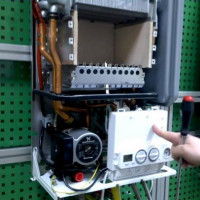 Beretta gas boiler malfunctions: how to decrypt the code and eliminate the malfunction
  Conord gas boiler malfunctions: common breakdowns and solutions
  How to increase the efficiency of a gas boiler with your own hands: the best ways to increase the efficiency of the boiler
  How much does it cost to connect gas to a private house: the price of organizing gas supply
  The best washing machines with dryer: model rating and customer tips
  What is the color temperature of light and the nuances of choosing the temperature of the lamps to suit your needs
  Replacement of a geyser in an apartment: replacement paperwork + basic norms and requirements