Viewing wells for drainage: types, arrangement and installation features

A high level of groundwater is a hydrogeological situation that negatively affects the technical condition of underground structures. Contacting with concrete or brick structures, water gradually but extremely persistently destroys them.
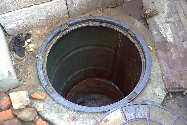
A drainage system is designed to lower the water level and drain water. One of its functional parts is manhole for drainage, necessary for the audit and cleaning of underground utilities.
Before proceeding with installation work, you should determine the optimal type of well, prepare the necessary materials and familiarize yourself with the installation instructions. All these questions have been studied in detail by us, and the answers to them are presented in this article.
The content of the article:
- Types of drainage inspection wells
- Types of drainage manholes
- Which material to prefer
- How to mount a viewing drainage well
- Excavation development and its dimensions
- The device base of the drainage well
- Installation or manufacture of the bottom
- Production of a receiving tray for pipes
- Mounting the first ring of the working chamber
- Installation of overlap and neck
- Waterproofing the working chamber
- Finishing work: filling and installation of the hatch
- Conclusions and useful video on the topic
Types of drainage inspection wells
The drainage manhole is an underground hydraulic structure designed to monitor the condition and periodically clean the system.
The shape of the well in the plan can be rectangular or round. They are used for pressure and pressureless drainage systems, but with some differences.
Usually, arrangement of drainage circuits made by a pressureless scheme. This is a network of interconnected drainage collectors, through which floodwater and infiltrated groundwater collected by drains moves by gravity. The force of gravity stimulates the movement of flows to the places of collection and disposal.
The pressure system is characterized by forced movement of effluents, the transportation of which is due to the operation of pumping equipment.
A pressure system is arranged where their spontaneous movement to storage for disposal and disposal or to treatment facilities for processing is not possible. For example, if it is not possible to install the drive below the drain level.
Both types of sewer systems are constructed according to SNiP 2.0403-85 “Sewerage. External networks and facilities. ”

Designs for Gravity Networks
When a pressure-free system device is calculated drain pipe slope. I lay the trunk in a straight line connecting the branches with wells.
It is necessary to provide viewing drainage wells in areas:
- direct drainage pipe for inspection and maintenance;
- accession and branching of the drainage pipeline;
- changes in the diameter of the drainage pipeline;
- changes in the slope of the drainage pipeline;
- changes in the direction of the current (rotary well).
For straight sections of the drainage pipeline, the maximum length is established, at which the device of the inspection well is required.
This value depends on the diameter of the pipeline:
- 35 m - Ø 150 mm and less;
- 50 m - from Ø 200 to 450 mm;
- 75 m - Ø 500 to 600 mm;
- 100 m - Ø 700 to 900 mm;
- 150 m - from Ø 1000 to 1400 mm;
- 200 m - from Ø 1500 to 2000 mm;
- 250-300 m - over Ø2000 mm.
Such a dependence of the length of the pipeline on the diameter is given in the normative documentation regulating the rules for the construction of all types of sewer systems. It is based on many years of construction, monitoring and maintenance practices.
The size of the inspection wells (working chamber in plan) also depends on the largest diameter D of the drainage pipe.
Values for rectangular wells:
- up to Ø 600 mm - 1000 mm for length and width;
- Ø 700 mm and more, - D + 400 mm for length and D + 500 mm for width.
Most manholes have a round-shaped working chamber.
The dependence of the diameter of the well Ø on the diameter of the pipe D:
- Ø 1000 mm - up to D 600 mm;
- Ø 1250 mm - D 700 mm;
- Ø 1500 mm - from D 800 mm to 1000 mm;
- Ø 2000 mm - D 1200 mm.
The dimensions of the pivot well can be increased to provide a minimum turning radius of the trays.
There are several reservations about the size of the manhole, related to the depth of the bottom of the structure:
- if the depth of the manhole is 1.2 m or less, for pipelines no more than 150 mm, a well with a diameter of 700 mm is allowed;
- for wells with a depth of 3 m or more, the minimum size of the working chamber is at least 1500 mm.
Shallow manholeswhich may be serviced and inspected from the surface are called inspection. Well structures requiring the submersion of the performer to a depth of more than 1 m are classified as serviced.

The height of the working chamber of the inspection well is measured from the bottom (base plate) to the upper edge of the neck. It depends on the depth of the drainage system and on its purpose: drainage of groundwater from the foundation or drainage of a private site.
The mouth of the well provides access for people and equipment inside the working chamber, the most suitable diameter for this is 700 mm. For descent into the working chamber, the inspection well is equipped with brackets or a ladder.
When arranging trays for drainage pipes, the height of the tray shelf is determined by the largest diameter of the pipe. The top lines of the tray shelves should be flush with the top of the pipe.

Manhole for pressure networks
Pressure pipelines do not need to observe slopes. In addition to standard functions, inspection wells of pressure networks form rational places for installation, adjustment and maintenance of equipment.
Arrange them at installation sites:
- locking equipment;
- pumping stations;
- in places of accession to highways.
The size of the working chamber depends on the equipment being installed. The depth should be 0.5 m deeper than the zero temperature penetration. If this is not possible, the well shaft should be insulated to the indicated depth.
The distance from the walls of the working chamber to the pipeline should be at least:
- 0.3 m for pipes Ø 400 mm and less;
- 0.5 m for pipes from Ø 500 to 600 mm;
- 0.7 m for pipes Ø 700 mm and more.
The height of the working chamber must be at least 1.5 m. For the descent, the well is equipped with iron brackets or stairs.

Types of drainage manholes
Viewing wells designed for a pressureless drainage system are divided into the following types:
- linear
- rotary;
- nodal with one or two attachment nodes.
The standard designs of factory-ready reinforced concrete manholes have been developed according to the 3.003.1-1 / 87 series “Prefabricated reinforced concrete, one-piece wells for underground pipelines”.

Linear wells arrange on straight sections of the pipeline, have two pipes: a supply and a discharge.
Swivel wells characterized by an acceptable angle of rotation of the pipeline, which depends on the diameter of the pipe and the size of the working chamber.
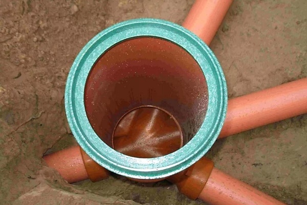
Nodal wells constructed so that the connected pipelines have an acute angle with the main pipeline in the direction of the fluid.

Which material to prefer
Viewing wells can be industrial or self-made. As a rule, the design of the well is agreed with the operating organization.
The industry offers various options for finished viewing drainage wells made of: concrete, polymers or composites. Wells of independent manufacture can additionally be made of brick, buta. Each material has its pros and cons.

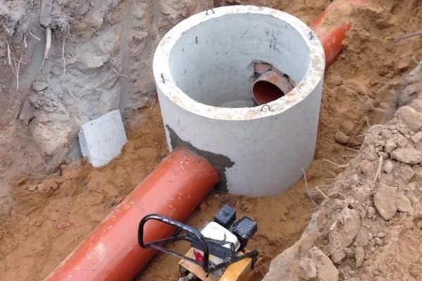
The vast majority of drainage wells are made of reinforced concrete rings.
The use of concrete has its advantages:
- excellent resistance to the buoyancy of water;
- ability to hold heavy loads;
- the possibility of manufacturing manually at the construction site;
- low price.
Reinforced concrete has a density of about 2.5 times that of water. It has a large mass and a high coefficient of friction with the surrounding soil, which well compensates for the buoyancy of water.
However, a large mass of concrete has its drawbacks:
- the need for lifting equipment;
- the difficulty of making holes for the input and output of drainage pipes;
- the need to equip access roads for the period of installation work;
- the inability to achieve full water resistance.
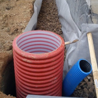
Composite and polymer viewing wells prefabricated can be used on pipelines up to 400 mm.

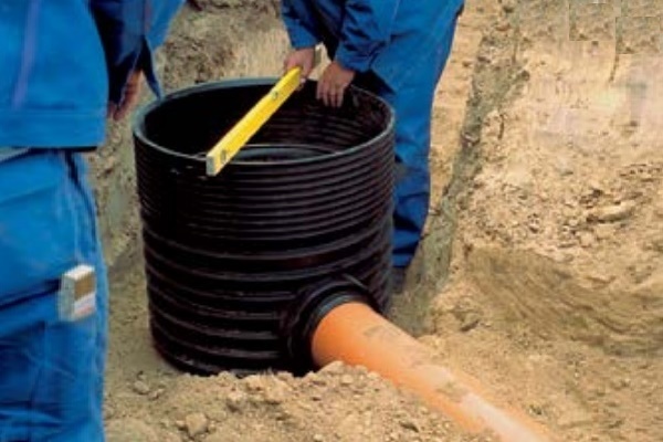
Modern urban development is increasingly using polymer drainage wells.
There are a number of reasons for this:
- ease of installation;
- wide selection of fittings;
- high speed of construction;
- tightness;
- light weight.
Transportation of polymer or composite wells is carried out by ordinary freight transport. Three people are enough to assemble and install the well.
However, such wells also have disadvantages:
- high price;
- lack of stability;
- manufacturing according to individual design data is very expensive.
When acquiring a plastic well, it is necessary to pay attention to the withstand loads, especially if the well is mounted within the carriageway.
Brick wells have pros and cons similar to concrete wells. An additional advantage of a brick well can be attributed to the simplicity of achieving a given size. However, such a well requires more time for construction.

How to mount a viewing drainage well
By the time the work on the installation of the drainage well begins, the pipeline should be laid, but not filled up.
General progress of construction work:
- digging pit;
- base unit;
- installation or manufacture of the bottom;
- manufacture or installation of a tray;
- mounting the well’s working chamber;
- Mounting the top of the working chamber and neck;
- waterproofing the working chamber;
- backfill and installation of the hatch.
Consider the option of building a factory readiness manhole. With self-construction, the construction stages are similar.
Excavation development and its dimensions
Before starting the development of the pit, you need to make sure that there is no ground water at the bottom of the well. If there is water, then it is necessary to build a temporary drainage pit or conduct periodic pumping.
The pit is produced according to the size of the well planned for the device. The bottom of the pit should be larger than the base of the future structure. The less dense the soil and the less clay particles in its composition, the less its ability to “hold” the production form.
Usually, when excavating a pit in loose, easily crumbling sandy soils, there is much more work to extract the dump than when developing a pit in sandy loam and loam. If shedding of gangue will interfere with the development of the pit, the walls of the excavation will need to be strengthened.
The depth of the pit is performed more by 35-40 cm of the lower mark of the drainage pipe. The pipe marks are checked with a level.

The device base of the drainage well
After the excavation is excavated, coarse gravel or gravel of a fraction of 10-20 mm is poured onto the bottom. Enough preparatory layer thickness of 20 cm.

Sand is covered with a layer of 10-15 cm on top of coarse rocks. Then it is abundantly moistened and thoroughly compacted. A good level of density of the base can be considered a seal in which a person’s foot does not sink into the sand (shoes do not leave prints).
Installation or manufacture of the bottom
The construction of the bottom is a crucial stage in the entire construction of the inspection well, since it is the bottom that takes the entire weight of the structure and determines its verticality.
There are two options: to make on-site manually or to mount the finished.
Option one. It is necessary to ensure that there is no water for at least 2 days, otherwise most of the binder will be washed out of concrete. The bottom thickness should be at least 10-15 cm.
For reinforcing the bottom using rods with a diameter of 6 mm. A mesh with a mesh size of about 10 cm is made of reinforcement.
First, fill in half the volume of concrete. After the bottom part is set, the mesh is laid and concrete is poured to the required thickness of the well base. The ends of the reinforcement along the perimeter of the bottom should be covered with concrete. This design is suitable for wells up to 10 m deep.
Option Two. The finished bottom is a reinforced concrete slab, mounted on a prepared and compacted base. The quality of installation is checked using the building level.

After performing all operations, the bottom of the well should be 5-10 cm lower than the lower point of the branch pipe.
Production of a receiving tray for pipes
A layer of cement mortar is laid on the mounted bottom and a bed for drainage pipes is formed. Using the level, the marks are checked.
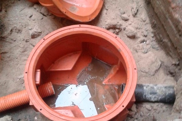
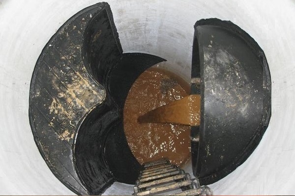
The bottom of the finished plastic well, as a rule, already has the necessary trays.

Mounting the first ring of the working chamber
Drain pipes must first be laid on the receiving trays. Bottom of the first concrete ring opposite the receiving trays, the corresponding holes are cut.
Installation of the fittings of the concrete well, sealing of joints and holes is carried out with cement mortar of grade 100.

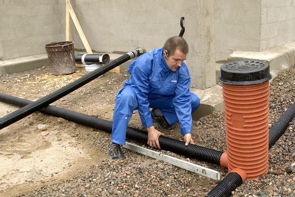
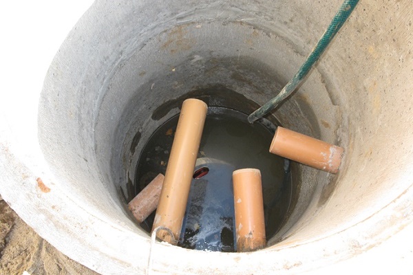
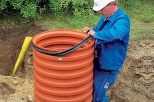
The working chamber of the plastic well is mounted as a whole.If there is a danger of underflooding of the pit, the well is placed under pressure before filling with soil.

Installation of overlap and neck
The top of the reinforced concrete served well is a floor slab. The standard opening for access to the shaft of the storage or collector structure should be 700 mm in diameter.
The opening of the inspection wells is accepted from 600 mm and more: it should provide free entry of devices for cleaning the network if necessary.
After installing the top of the working chamber, functional equipment for pressure drainage is installed.
Next is the arrangement of the neck of the well. The number and size of rings is selected taking into account the required height.
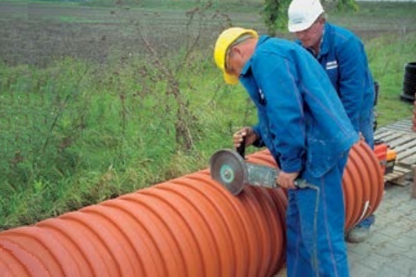
The neck of some plastic wells is a cone-shaped short pipe, which can easily be cut to the required size.
The neck is blocked by a support ring under the hatch.

For a plastic well, the top and neck are shaped parts installed on the seal.
In the case of self-manufacture, the top of the working chamber is designed to withstand the weight of soil, pedestrians, vehicles, if the structure is arranged under the roadway. It is made of reinforced concrete, according to the technology of manufacturing the bottom.
Waterproofing the working chamber
In the event that ground or flood water can come into contact with an inspection well, the walls are waterproofed 500 mm above its level during the period of the greatest rainfall.
For well waterproofing coating waterproofing based on bituminous mastic is used, it is applied:
- on the bottom and the working chamber of the well;
- on cement joints, entry points of drainage pipes.
Additionally, from the outside of the well, pipes are sealed with a clay lock.
Instead of bitumen mastic, specialized waterproofing compounds can be used. Waterproofing is applied to the inner surface of the well. Additives increase the waterproofing properties of the solution to the composition of the masonry mortar.

Finishing work: filling and installation of the hatch
Mount on the neck of the well sewer manhole.
The installation level of the hatch depends on the type of coating:
- on the carriageway - level with the carriageway;
- in the green zone - 50-70 mm above ground level;
- in undeveloped part - 200 mm above ground level.
The filling around the well is made with a gravel-sand mixture. A layer of about 20 cm is poured at a time, after which the soil is compacted. To facilitate tamping, it can be shed with water.
Partial entry of the soil-plant layer into the backfill is extremely undesirable, since it includes organic substances. Over time, the organic matter will decompose and decrease in volume, and the earth around the well will sag.

Conclusions and useful video on the topic
Installation of a plastic well:
Comparison of plastic wells:
The manholes installed on the drains are part of the hydraulic system. With proper design and execution, they require a one-time service of 5 years. At the same time, the service life is measured for decades.
Have experience in arranging viewing drainage wells? Or have questions about the topic? Please share your opinion and leave comments. The feedback form is located below.
 Plastic wells for drainage: device, types, classification, installation instructions
 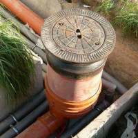 Plastic sewer wells: varieties + installation features
 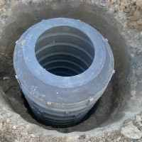 Polymer-sand wells: device, advantages and disadvantages, installation rules
 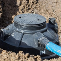 Sewer wells: full classification and examples of arrangement
  Sewer polymer hatches: types and characteristics + features of use
 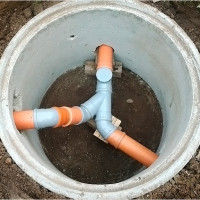 Manhole for sewage: installation of a well in storm and sewage systems
  How much does it cost to connect gas to a private house: the price of organizing gas supply
  The best washing machines with dryer: model rating and customer tips
  What is the color temperature of light and the nuances of choosing the temperature of the lamps to suit your needs
  Replacement of a geyser in an apartment: replacement paperwork + basic norms and requirements
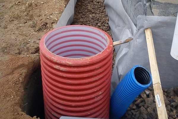
In our factory, during the reconstruction of the drainage system, all concrete manholes were replaced with polymer ones. I read that for their use it is necessary to draw up an individual plan - a project, and to remodel the entire drainage system completely, and not partially, as we did. In general, I have a question: what problems can arise with such a replacement? And can they somehow be eliminated without altering the system?
It is impossible to say unequivocally, since in general terms the whole situation as a whole is not clear. The project to replace the inspection wells, especially at the enterprise, had to be agreed with someone without fail.
Well, it cannot be that they take and simply replace the concrete manholes with plastic ones, without taking into account the current operation of the drainage system as a whole.
If the replacement was made taking into account the design of the current system, then difficulties should not arise. If the replacement was made without taking into account the design features and current characteristics, then the following problems are possible:
- blockages;
- deformation under heavy loads;
- violation of tightness.
I advise you not to eliminate anything if there are problems, since they should be solved by specialists who were involved in the installation of inspection wells.