Pinout of different types of USB connectors: pinout of micro and mini usb contacts + nuances of desoldering
The USB interface is a popular form of technological communication on mobile and other digital devices. Connectors of this kind are often found on personal computers of various configurations, peripheral computer systems, on cell phones, etc.
A feature of the traditional interface is a small-sized USB pinout. For work, only 4 pins (contacts) + 1 grounding shielding line are used. True, the latest more advanced modifications (USB 3.0 Powered-B or Type-C) are characterized by an increase in the number of working contacts. What we will talk about in this material. We also describe the structure of the interface and the features of the cable wiring on the connector pins.
The content of the article:
Types of USB Connectors
The abbreviation "USB" carries an abbreviation, which in its entirety reads as "Universal Series Bus" - a universal serial bus, thanks to which high-speed digital data exchange is carried out.
The versatility of the USB interface is noted:
- low power consumption;
- unification of cables and connectors;
- simple logging of data exchange;
- high level of functionality;
- wide support for drivers of different devices.
What is the structure of the USB interface, and what types of USB technology connectors exist in the modern world of electronics? Let's try to figure it out.
Technological structure of the USB 2.0 interface
The connectors related to products included in the group of specifications 1.x - 2.0 (created before 2001) are connected to a four-wire electric cable, where two conductors are power supply and two more - transmitting data.
Also, in specifications 1.x - 2.0, the wiring of service USB connectors suggests connecting a shielding braid - in fact, the fifth conductor.
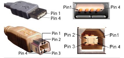
Existing versions of universal serial bus connectors of the marked specifications are represented by three options:
- Normal - Type “A” and “B”.
- Mini - Type “A” and “B”.
- Micro - Type “A” and “B”.
The difference between all three types of products lies in the design approach. If normal connectors are intended for use on stationary equipment, mini and micro connectors are made for use in mobile devices.
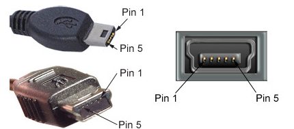
Therefore, the last two types are characterized by a miniature design and a slightly modified connector shape.
Pinout table of standard connectors of type "A" and "B"
| Contact | Specification | Cable conductor | Function |
| 1 | Power + | Red (orange) | + 5V |
| 2 | Data - | White (gold) | Data - |
| 3 | Data + | Green | Data + |
| 4 | Nutrition - | Black blue) | Land |
Along with the performance of mini-A and mini-B connectors, as well as micro-A and micro-B connectors, there are modifications of mini-AV and micro-AV connectors.
A distinctive feature of such structures is the execution of the wiring of USB conductors on a 10-pin contact pad. However, in practice, such connectors are rarely used.
Micro USB and Mini USB interface pinouts for “A” and “B” type connectors
| Contact | Specification | Cable conductor | Function |
| 1 | Power + | Red | + 5V |
| 2 | Data - | White | Data - |
| 3 | Data + | Green | Data + |
| 4 | Identifier | – | Host device |
| 5 | Nutrition - | The black | Land |
Technological structure of USB 3.x interfaces
Meanwhile, the improvement of digital equipment by the time of 2008 led to the moral aging of specifications 1.x - 2.0.
These types of interface did not allow the connection of new equipment, for example, external hard drives, in such a way as to provide a higher (more than 480 Mb / s) data transfer rate.
Accordingly, a completely different interface appeared, marked with specification 3.0. The development of a new specification is characterized not only by increased speed, but also gives an increased current strength of 900 mA versus 500 mA for USB 2/0.
It is clear that the appearance of such connectors provided service for a larger number of devices, some of which can be powered directly from the universal serial bus interface.
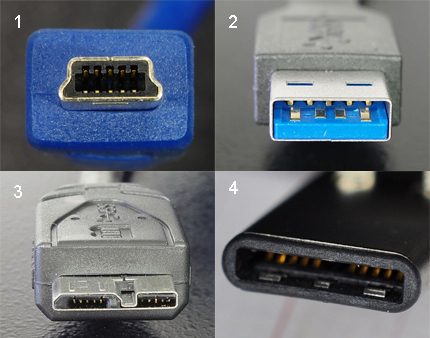
As you can see in the picture above, interfaces of the third specification have more working contacts (pins) than the previous - second version. However, the third version is fully compatible with the "two".
To be able to transmit signals at a higher speed, the developers of the designs of the third version were equipped with an additional four data lines and one line of the zero contact wire. Augmented contact pins are arranged in a separate row.
Table of designation of pins of connectors of the third version for wiring the USB cable
| Contact | Execution "A" | Execution "B" | Micro-b |
| 1 | Power + | Power + | Power + |
| 2 | Data - | Data - | Data - |
| 3 | Data + | Data + | Data + |
| 4 | Land | Land | Identifier |
| 5 | StdA_SSTX - | StdA_SSTX - | Land |
| 6 | StdA_SSTX + | StdA_SSTX + | StdA_SSTX - |
| 7 | GND_DRAIN | GND_DRAIN | StdA_SSTX + |
| 8 | StdA_SSRX - | StdA_SSRX - | GND_DRAIN |
| 9 | StdA_SSRX + | StdA_SSRX + | StdA_SSRX - |
| 10 | – | – | StdA_SSRX + |
| 11 | Shielding | Shielding | Shielding |
Meanwhile, the use of the USB 3.0 interface, in particular the “A” series, was a serious design flaw. The connector has an asymmetric shape, but it does not specifically indicate the connection position.
The developers had to deal with the modernization of the design, as a result of which in 2013, the USB-C option appeared at the disposal of users.
Upgraded USB 3.1
The design of this type of connector involves duplication of the working conductors on both sides of the plug. Also on the interface there are several redundant lines.
This type of connector is widely used in modern mobile digital technology.
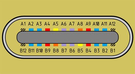
It is worth noting the characteristics of USB Type-C. For example, the speed parameters for this interface show a level of 10 Gbit / s.
The design of the connector is made in a compact design and provides a symmetrical connection, allowing insertion of the connector in any position.
Pinout table compliant with specification 3.1 (USB-C)
| Contact | Designation | Function | Contact | Designation | Function |
| A1 | GND | Grounding | B1 | GND | Grounding |
| A2 | SSTXp1 | TX + | B2 | SSRXp1 | Rx + |
| A3 | SSTXn1 | TX - | B3 | SSRXn1 | RX - |
| A4 | Tire + | Power + | B4 | Tire + | Power + |
| A5 | CC1 | CFG Channel | B5 | SBU2 | PPD |
| A6 | Dp1 | USB 2.0 | B6 | Dn2 | USB 2.0 |
| A7 | Dn1 | USB 2.0 | B7 | Dp2 | USB 2.0 |
| A8 | SBU1 | PPD | B8 | CC2 | CFG |
| A9 | Tire | Nutrition | B9 | Tire | Nutrition |
| A10 | SSRXn2 | RX - | B10 | SSTXn2 | TX - |
| A11 | SSRXp2 | Rx + | B11 | SSTXp2 | TX + |
| A12 | GND | Grounding | B12 | GND | Grounding |
The next level of USB 3.2 specification
Meanwhile, the process of improving the universal serial bus is actively continuing. At the non-profit level, the following specification level has already been developed - 3.2.
According to available information, the speed characteristics of an interface like USB 3.2 promise twice as much parameters as the previous design is capable of.
The developers managed to achieve such parameters by introducing multiband channels through which transmission is carried out at speeds of 5 and 10 Gbit / s, respectively.
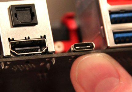
By the way, it should be noted that the compatibility of a promising interface with an existing USB-C is fully supported, since the Type-C connector (as already noted) is endowed with redundant contacts (pins) that provide multi-band signal transmission.
Features of the cable wiring on the connector pins
By some special technological nuances, the soldering of cable conductors on the contact pads of the connectors is not noted. The main thing in such a process is to ensure color matching beforehand. insulated cable conductors to a specific contact (pin).
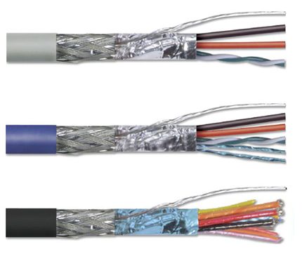
Also, if you are soldering modifications of outdated versions, you should consider the configuration of the connectors, the so-called “father” and “mother”.
The conductor soldered on the contact of the “father” should correspond to the soldering on the contact of the “mother”. Take, for example, the option of soldering the cable to the USB 2.0 contacts.
The four working conductors used in this embodiment are usually indicated by four different colors:
- in red;
- white
- green
- in black.
Accordingly, each conductor is soldered to a contact pad marked with a specification of a connector of a similar color. This approach greatly facilitates the work of the electronics engineer, eliminates possible errors in the wiring process.
A similar soldering technology applies to connectors of other series. The only difference in such cases is the greater number of conductors that have to be soldered. To simplify your work, it is convenient to use a special tool - a reliable soldering iron for soldering wires at home and stripper to remove insulation from the ends of the cores.
Regardless of the configuration of the connectors, soldering of the screen conductor is always used. This conductor is soldered to the corresponding pin on the connector, Shield - protective screen.
There are frequent cases of ignoring the protective screen when “specialists” do not see the point in this guide. However, the lack of a screen dramatically reduces the performance of the USB cable.
Therefore, it is not surprising when, with a significant cable length without a screen, the user receives problems in the form of interference.
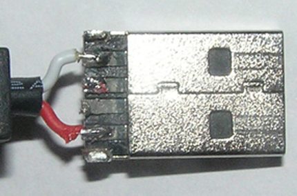
Soldering a USB cable is possible in different ways, depending on the configuration of the port lines on a particular device.
For example, to connect one device to another in order to obtain only the supply voltage (5V), it is enough to solder only two lines on the corresponding pins (contacts).
Conclusions and useful video on the topic
The video below illustrates the main points of pinout of the 2.0 series connectors and others, visually explains the individual details of the soldering procedures.
Having complete information on pinout of universal serial bus connectors, you can always cope with the technical problem associated with conductor defects. Also, this information will come in handy if you need to connect non-standard digital devices.
Would you like to supplement the above material with useful comments or valuable self-wiring tips? Write comments in the block below, add, if necessary, unique photo materials.
Maybe you still have questions after reading the article? Ask them here - our experts and competent site visitors will try to clarify incomprehensible points.

 RJ45 twisted pair cable pinout: wiring diagrams and crimping rules
  Types of cables and wires and their purpose: description and classification + decoding of marking
  Crimping twisted pair 8 and 4 cores: basic schemes + step-by-step briefing of crimping
  What is a vvg cable: decryption, characteristics + subtleties of cable selection
  Colors of wires in electrics: standards and labeling rules + methods for determining the conductor
  How to crimp an RJ-45 Internet cable with your own hands: ways + instructions for crimping an Internet connector
  How much does it cost to connect gas to a private house: the price of organizing gas supply
  The best washing machines with dryer: model rating and customer tips
  What is the color temperature of light and the nuances of choosing the temperature of the lamps to suit your needs
  Replacement of a geyser in an apartment: replacement paperwork + basic norms and requirements