Machine selection by load power, cable cross-section and current: principles and formulas for calculations

For the organization of faultlessly functioning intra-house power supply, it is necessary to allocate separate branches. Each line must be equipped with its own protective device that protects the cable insulation from fusion. However, not everyone knows which device to purchase. Do you agree?
You will learn all about the choice of machines according to load power from the article we presented. We will tell you how to determine the rating for a circuit breaker of the required class. Taking into account our recommendations guarantees the purchase of the required devices that can eliminate threatening situations during the operation of the wiring.
The content of the article:
Circuit Breakers for Domestic Networks
Electricity supply organizations carry out the connection of houses and apartments, performing work on connecting the cable to the switchboard. All activities for the installation of wiring in the room are carried out by its owners, or by hired specialists.
To choose an automatic machine to protect each individual circuit, you need to know its rating, class and some other characteristics.
Key parameters and classification
Household machines are installed at the entrance to a low-voltage electric circuit and they are designed to solve the following problems:
- manual or electronic switching on or off of the electric circuit;
- circuit protection: blackout with a slight prolonged overload;
- circuit protection: instantaneous current cut-off during short circuit.
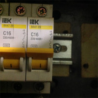
Each switch has a characteristic expressed in amperes, which is called rated current (In) or “face value”.
The essence of this value is easier to understand using the excess coefficient:
K = I / In,
where I is the real current strength.
- K <1.13: disconnection (trip) will not occur within 1 hour;
- K> 1.45: shutdown will occur within 1 hour.
These parameters are fixed in clause 8.6.2. GOST R 50345-2010.To find out how long a trip will occur at K> 1.45, you need to use a graph that reflects the time-current characteristic of a particular machine model.

Also, each type of circuit breaker has a current range (Ia), in which the instant trip mechanism is triggered:
- class “B”: Ia = (3 * In .. 5 * In];
- class “C”: Ia = (5 * In .. 10 * In];
- class “D”: Ia = (10 * In .. 20 * In].
Type “B” devices are mainly used for lines that are of considerable length. Class “C” circuit breakers are used in residential and office premises, and devices marked “D” protect circuits where there is equipment with a large starting current coefficient.
The standard line of household machines includes devices with ratings of 6, 8, 10, 16, 20, 25, 32, 40, 50 and 63 A.
The design of the releases
In modern circuit breaker There are two types of releases: thermal and electromagnetic.
The bimetallic release is in the form of a plate made of two conductive metals with different thermal expansion. Such a design, with prolonged exceeding of the nominal value, leads to heating of the part, its bending and triggering of the circuit opening mechanism.
In some machines, using the adjusting screw, you can change the current at which the trip occurs. Previously, this technique was often used to “fine-tune” the device, but this procedure requires in-depth specialized knowledge and several tests.

Now on the market you can find many models of standard ratings from different manufacturers, whose time-current characteristics are slightly different (but at the same time comply with regulatory requirements). Therefore, it is possible to choose a machine with the necessary “factory" settings, which eliminates the risk of incorrect calibration.
An electromagnetic release prevents overheating of the line as a result of a short circuit. It reacts almost instantly, but at the same time, the value of the current strength must be several times higher than the nominal value. Structurally, this part is a solenoid. Overcurrent generates a magnetic field that moves the core, opening the circuit.
Compliance with the principles of selectivity
In the presence of a branched electric circuit, it is possible to organize protection in such a way that, in the event of a short circuit, only the branch on which the emergency occurs is switched off. For this, the principle of selectivity of switches is used.

To ensure selective shutdown, automatic devices with instant cut-off are installed on the lower steps, opening the circuit in 0.02 - 0.2 seconds. The circuit breaker, located at a higher stage, either has a tripping delay of 0.25 - 0.6 s or is made according to a special “selective” circuit in accordance with DIN VDE 0641-21.
For guaranteed security selective operation of automatic machines it is better to use machines from one manufacturer. For circuit breakers of a single model range, there are selectivity tables that indicate possible combinations.
Simple installation rules
The part of the circuit that must be protected with a circuit breaker can be single or three phase, have a neutral, as well as a PE wire (ground). Therefore, the machines have from 1 to 4 poles, which lead a conductive core.When conditions are created for tripping, all contacts are simultaneously disconnected.

The machines are installed as follows:
- unipolar per phase;
- bipolar for phase and neutral;
- three-pole into 3 phases;
- four-pole into 3 phases and neutral.
It is forbidden to do the following:
- install single-pole circuit breakers on neutral;
- insert PE wire into the machine;
- install three single-pole devices instead of one three-pole circuit-breaker if at least one three-phase consumer is connected to the circuit.
All these requirements are spelled out in the EMP and must be observed.
In each house or room to which electricity is connected, an introductory machine is installed. Its value is determined by the supplier and this value is spelled out in the contract for the connection of electricity. The purpose of such a switch is to protect the section from the transformer to the consumer.
After the introductory machine, a counter is connected to the line (single or three phase) and residual current device, whose functions differ from the operation of a circuit breaker and differential switch.
If the room is wired into several circuits, then each of them is protected by a separate machine, the power of which indicated on the marking. Their ratings and classes are determined by the owner of the premises, taking into account the existing wiring or the power of the connected devices.

When choosing a place to place switchboard it must be remembered that the air temperature affects the properties of the thermal release. Therefore, it is advisable to have a rail with machines inside the room.
Calculation of the required face value
The main protective function of the circuit breaker extends to the wiring, so the rating is carried out along the cable cross section. In this case, the entire circuit should ensure the regular operation of the devices connected to it. The calculation of the system parameters is simple, but many nuances must be taken into account to avoid errors and problems.
Determining the total capacity of consumers
One of the main parameters of the electric circuit is the maximum possible power of the consumers of electricity connected to it. When calculating this indicator, you can’t just summarize the passport data of the devices.
Active and rated component
For any device powered by electricity, the manufacturer must indicate the active power (P) This value determines the amount of energy that will be irrevocably converted as a result of the apparatus and for which the user will pay on the meter.
But for devices with capacitors or an inductor, there is another power with a non-zero value, which is called reactive (Q) She reaches the device and almost instantly returns back.
The reactive component does not participate in the calculation of the used electricity, but together with the active one forms the so-called “full” or “rated” power (S), which gives a load to the circuit.

It is necessary to consider the contribution of a separate device to the total load on the conductive wires and the machine according to its full power: S = P / cos (f).
Increased starting currents
The next feature of some types of household appliances is the presence of transformers, electric motors or compressors. Such devices at the start of operation consume a starting (starting) current.
Its value can be several times higher than the standard indicators, but the operating time at high power is small and usually ranges from 0.1 to 3 seconds. Such a short-term surge will not lead to the operation of the thermal release, but the electromagnetic component of the circuit breaker, which is responsible for overcurrent short circuit, can react.
This situation is especially relevant for leased lines to which equipment such as woodworking machines are connected. In this case, you need to calculate the amperage and, perhaps, it makes sense to use a class “D” automaton.
Demand factor
For circuits to which a large amount of equipment is connected and there is no device that consumes the largest part of the current, a demand coefficient (ks) The meaning of its application is that all devices will not work simultaneously, so the summation of the rated power will lead to an overestimated rate.

This coefficient may take a value equal to or less than one. Estimated power calculations (Pr) of each device occurs according to the formula:
Pr = ks * S
The total rated power of all devices is used to calculate the circuit parameters. The use of the demand coefficient is advisable for office and small retail premises with a large number of computers, office equipment and other equipment powered from one circuit.
For lines with a small number of consumers, this coefficient is not used in its pure form. From the power count, those devices are removed whose inclusion at the same time as more energy-consuming devices is unlikely.
So, for example, there is little chance of a one-time job in a living room with an iron and a vacuum cleaner. And for workshops with a small number of personnel, only 2-4 of the most powerful power tools are taken into account.
Current calculation
The choice of an automaton is made according to the maximum value of the current strength permissible in the circuit section. It is necessary to obtain this indicator, knowing the total power of electric consumers and the voltage in the network.
According to GOST 29322-2014, from October 2015, the voltage value should be equal to 230 V for an ordinary network and 400 V for a three-phase one. However, in most cases, the old parameters are still valid: 220 and 380 V, respectively. Therefore, for the accuracy of the calculations, it is necessary to carry out measurements using a voltmeter.

Another issue especially relevant to private wiring, is the provision of power supply with insufficient voltage. Measurements on such problematic objects may show values that fall outside the range specified by GOST.
Moreover, depending on the level of electricity consumption by neighbors, the voltage value can vary greatly over a short period of time.
This creates a problem not only for the operation of the devices, but also for calculating current. When the voltage drops, some devices simply lose power, and some, which have an input stabilizer, increase electricity consumption.
It is difficult to qualitatively calculate the necessary circuit parameters under such conditions. Therefore, you will either have to lay cables with a known large cross section (which is expensive), or solve the problem by installing an input stabilizer or connecting the house to another line.

After the total power of electrical appliances was found (S) and the voltage value (U), calculation of current strength (I) carried out according to the formulas resulting from Ohm's law:
If = S / Uf for single-phase network
Il = S / (1.73 * Ul) for three-phase network
Here is the index “f"Means phase parameters, and"l”- linear.
Most three-phase devices use the “star” connection type, and it is precisely according to this scheme that a transformer is operating that produces current for the consumer. With a symmetrical load, the linear and phase forces will be identical (Il = If), and the voltage is calculated by the formula:
Ul = 1.73 * Uf
The nuances of selecting a cable section
The quality and parameters of wires and cables are regulated by GOST 31996-2012. According to this document, technical specifications are developed for the products, where a certain range of values of basic characteristics is allowed. The manufacturer must provide a table of correspondence of the cross section of the cores and the maximum safe current strength.

It is necessary to choose a cable in such a way as to ensure the safe flow of current corresponding to the calculated total power of electrical appliances. According to the PUE (Electrical Installation Rules), the minimum design cross-section of wiresused in residential premises must be at least 1.5 mm2.
Standard sizes have the following meanings: 1.5; 2.5; 4; 6 and 10 mm2.
Sometimes there is a reason to use wires with a cross section one step larger than the minimum allowable. In this case, there is the possibility of connecting additional devices or replacing existing ones with more powerful ones without expensive and lengthy work on laying new cables.
Calculation of the parameters of the machine
For any circuit, the following inequality must be satisfied:
In <= Ip / 1.45
Here In - rated current of the machine, and Ip - allowable current for wiring. This rule ensures guaranteed tripping over prolonged exceeding the permissible load.

The machine rating can be calculated both by the total load, and by the cross section of the wires of the already laid wiring. Suppose that there is a connection diagram for electrical appliances, but the wiring has not yet been laid.
In this case, the sequence of actions is as follows:
- Calculation of the total current strength of electrical appliances connected to the network.
- The choice of an automaton with a face value of no less than the calculated value.
- Selection of cable cross-section at the rating of the machine.
Example:
- S = 4 kW; I = 4000/220 = 18 A;
- In = 20 A;
- Ip > = In * 1.45 = 29 A; D = 4 mm2.
If the wiring has already been laid, then the sequence of actions is different:
- Determination of permissible current with a known section and method of wiring according to the table provided by the manufacturer.
- Selection of circuit breaker.
- Calculation of the power of connected devices. Manning a group of devices so that the total load on the circuit is less than the nominal value.
Example. Let two single-core cables be laid in an open way, D = 6 mm2then:
- Ip = 46 A;
- In <= Ip / 1.45 = 32 A;
- S = in * 220 = 7.0 kW.
In paragraph 2 of the last example, there is a slight allowable approximation. Exact value of In = Ip / 1.45 = 31.7 A rounded to 32 A.
Choosing between multiple values
Sometimes a situation arises when you can select several machines with different ratings to protect the circuit. For example, with a total power of electrical appliances 4 kW (18 A), a wiring with a cross section of copper conductors of 4 mm was selected with a margin2. For this combination, you can put the switches on 20 and 25 A.

The advantage of choosing the switch with the highest rating is the ability to connect additional devices without changing the circuit elements. This is most often done.
In favor of choosing an automaton with a lower nominal value, the fact that its thermal release will respond more quickly to an increased current indicator is in favor.The fact is that some devices may have a malfunction, which will lead to an increase in energy consumption, but not to a short circuit value.
For example, a breakdown of the motor bearing of the washing machine will lead to a sharp increase in current in the winding. If the machine quickly responds to exceeding the permitted values and trips, the motor will not burn.
Conclusions and useful video on the topic
The design of the circuit breaker and its classification. The concept of time-current characteristics and the selection of nominal cable cross-section:
Calculation of the power of devices and the choice of machine using the provisions of the PUE:
The choice of a circuit breaker should be taken responsibly, since the safety of the electrical system at home depends on this. With all the many input parameters and nuances of the calculation, it must be remembered that the main protective function of the machine extends to the wiring.
Please write comments, ask questions, post a photo on the topic of the article in the block below. Share useful information that may be useful to site visitors. Tell us about your experience in choosing circuit breakers to protect your country or home wiring.
 Denominations of current circuit breakers: how to choose the right automaton
 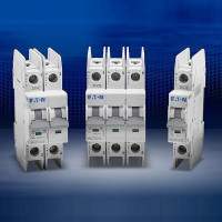 Choosing a circuit breaker: types and characteristics of automatic machines
  What is the selectivity of circuit breakers + principles of calculation of selectivity
 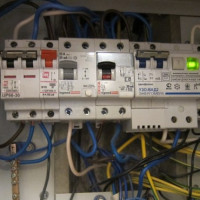 What is the difference between an RCD from a differential automaton and what is better to use?
 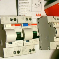 How to choose the right RCD by capacity: existing types of RCD + subtleties of choice
  Marking circuit breakers: how to choose the right machine for wiring
  How much does it cost to connect gas to a private house: the price of organizing gas supply
  The best washing machines with dryer: model rating and customer tips
  What is the color temperature of light and the nuances of choosing the temperature of the lamps to suit your needs
  Replacement of a geyser in an apartment: replacement paperwork + basic norms and requirements