Vacuum switch: device and principle of operation + nuances of choice and connection

Electrical appliance vacuum circuit breaker is a device designed for operation as part of high-voltage electrical networks. It got its name from the design feature - the vacuum chamber, due to which the instantaneous extinction of the electric arc is achieved.
The device is used as switches designed to shut down equipment in case of emergency or as part of ongoing operation. Let's take a closer look at what a vacuum switch is and what it is for.
The content of the article:
How does a high voltage vacuum switch work?
The basis of the functionality of the vacuum chambers used in the design of circuit breakers are the physical properties of a gas in a discharged state. Under such conditions, the property of the gas, characterized as electric strength, changes significantly upward.
This effect of a high discharged medium (range from 10-6 to 10-8 N / cm2) has been successfully used in circuit breaker designs supplemented by gas vacuum chambers through which electrical contact groups pass.

The current flowing through the contact groups (at the moment the contact is split) forms an electric discharge - an arc. Arc burning occurs due to partial ionization of metal vapor, which inevitably forms from high temperature. The passage of current between the contacts through the formed plasma is maintained until the current passes to the zero bus.
As soon as the moment of transition through "zero" comes, the electric arc goes out. The total process time takes no more than 7-10 microseconds.
The device switches vacuum execution
A variety of vacuum circuit breakers, taking into account their design, is quite large. Therefore, it is difficult to give a characteristic of these devices in general. Meanwhile, regardless of the design differences, the principle of action remains unchanged.

Consider for general reference three-pole vacuum circuit breakerequipped with a spring-motor drive. This appliance is designed for indoor or outdoor installation. In any case, its installation is carried out inside special metal distribution boxes.
Devices can be operated in various sectors of the economy. However, there are some limitations.
So, vacuum circuit breakers are not intended for installation with subsequent operation in the following conditions:
- premises where there is a fire, explosive atmosphere;
- Installations constructively providing for frequent switching;
- mobile (mobile) type installations;
- power systems of sea and river vessels.
Vacuum circuit breakers typically have two design types:
- For stationary installation.
- For installation with a hardware trolley.
Regardless of the execution, the housing area of the device contains three poles equipped with arcing chambers.
Movable contactors operated by a spring-motor mechanism operate inside the vacuum chambers. The instrument housing is supplemented by a front panel, which contains display elements and control devices.

The three poles of the main circuit are made in the form of columns. The location of the poles, as a rule, on the rear of the chassis of the spring-motor drive. Each pole is supplemented by an arc quenching chamber, which is enclosed inside a polymer insulator. In order to enhance the electric strength, the insulator body has a ribbed shape.
Inside each vacuum chamber, a contact group of two elements is mounted - movable, fixed. The movable contact element through the traction insulator is connected to the switching mechanism. Further communication with the lower contact terminal. A fixed contact through a tapered fit is connected to the upper contact terminal of the device.
How does the circuit breaker drive work?
The movable contacts of the vacuum chambers are mechanically connected to the shaft of the spring-motor drive. Due to the power spring pre-charged (set in tension), the drive can be easily activated by simply pressing the control button or other mechanism.

A spring (usually two springs) is cocked by a chain drive. The normal mode of operation of the equipment involves the spring charging by means of an electric motor equipped with a gearbox. At the same time, there is a manual cocking handle, which is used in case of accidents or loss of power.
The charged spring is fixed by the trigger. This mechanism is controlled through an electromagnetic drive or through a power button. As soon as the switching mode is activated, the locking is released, the tensile force of the spring drives the cam mechanism. That, in turn, acts on the shaft, which is mechanically connected to the switching mechanism of the moving contacts of the vacuum chambers.
The operation to turn off the vacuum circuit breaker is performed by activating the "Disconnected" mode - an electromagnet or a button. The sequence of actions is almost the same as the first mode. It also involves tripping power springs, the state of which is set by the tripping trigger.

Convenience of operation and control of the device provides a control panel. On the front of the panel there are elements: counter of the number of cycles, status indicator of the spring of the cocking, status indicator of the vacuum circuit breaker.
Features of roll-out structures
Roll-out equipment is assembled on the basis of a special hardware trolley. With this accessory, a switch is inserted into or out of the cabinet.
The equipment trolley acts not only as a device transport, but also acts as a controller for turning the device into test mode or into operating mode as soon as the switch is pushed into the cabinet.

The vacuum switch is fixed directly to the moving part of the trolley. Fasteners are bolted. Meanwhile, the equipment trolley also has a fixed part, where the drive of the moving part is fixed. The movement of the movable module relative to the stationary one is carried out by the screw of the truck control handle.
The moving part is a metal base on four wheels, treated with a galvanic coating. Here there is an external mechanical interlock (push bar) of the ground electrode, lock of the drive screw, block contacts, circuit breaker locking mechanism and other elements that provide movement or fixation.
Installation and connection of the device
Before starting to install a vacuum circuit breaker, it is necessary to inspect all externally accessible elements in order to make sure that there are no damages or defects. Then, the insulating surfaces of the poles are cleaned with a dry lint-free cloth.
It is not allowed to introduce equipment into the system if chips, cracks, and deformed sections are present on insulating surfaces. The circuit of the secondary circuits, as well as the connection of the chassis bus, must be checked.

Before installation, the operation of the circuit breaker should be checked by the method of manual inclusion (idle without power) and make sure the position of the control panel indicators is correct. Then you need to check for the presence of the pole covers. If equipment with a rating of 1600A or higher is used, the protection covers must be removed before installation.
Connect directly to the network
The terminals of the contact tips of the conductors of the power cables must be stripped before connecting to the terminals of the switch.
The stripping procedure differs depending on the terminal material used:
- For copper and aluminum terminals without additional coating, the cleaning is carried out with sandpaper with a grain of M20 or lower, followed by degreasing of the metal surface.
- If the terminals are copper or aluminum coated with a layer of silver, it is sufficient to clean them with a lint-free cloth.
It is not permissible to use cables whose silver-plated terminals are damaged over an area of more than 5%. In this case, the damaged element must be replaced.More information on terminals for connecting wires can be found in this stuff.
External conductors are brought to the terminals of the vacuum circuit breaker in such a way that mechanical forces are not created on the terminals of the device from the side of the external conductors. Connections are made by means of a bolted coupling using flat elastic metal washers.
How is grounding made?
Stationary devices are connected to the “earthen” site by means of a bolted connection (M12) directly at the point indicated by the marking “Grounding”.

The area of the Earthing contact point must be degreased before connection. A grounding conductor should choose a bus of sufficient cross-section (Electrical Installation Rules), a flexible wire or a conductor woven with a bundle. Before laying the conductor on the contact pad of the contact surface, grease with special grease (TsIATIM-203).
The draw-out type is earthed using the elements of the equipment trolley. Grounding of the vacuum circuit breaker is carried out through the design of the equipment trolley, for which there are also fasteners.
Commissioning the device
The device is put into operation after an additional check of installed and prepared equipment. In particular, the reliability of grounding, the condition of the fasteners of the assembly components, and the access of the cooling medium to potentially heating elements are checked.
Surfaces of current-carrying rods in contact with lamellas of socket contact groups must be treated with a small amount of CIATIM lubricant. In general, it is necessary to carry out all the procedures provided by the EMP in the event of acceptance tests, and make sure that the operating voltage corresponds to the permissible limits.

Vacuum circuit breaker may be controlled by personnel authorized to service electrical installations operating at voltages above 1000 volts. The approved admission group for service persons must be at least the third. Before starting work with equipment, personnel undergo a technical minimum in order to study the intricacies of a particular model of equipment.
How to choose a vacuum circuit breaker?
The device is selected taking into account its nominal parameters, which are considered relative to the parameters of the current network at the installation site. The choice is made according to the criterion of the most loaded operating modes assumed for operating conditions.
The rated voltage of the vacuum circuit breaker is allowed to be equal (or increased) with respect to the rated voltage of the system fed through the switch.
The parameter of the rated long-term current is selected above the rated current of the supplied system. The rated cut-off current parameter is selected above the maximum value rated current Short circuit (the moment of divergence of contacts is taken into account).

From the point of view of possible short-circuit conditions, the choice is made taking into account the most difficult conditions.
The aperiodic component is calculated taking into account the short-circuit conditions with zero voltage in any of the phase lines. In this case, the aperiodic current parameter set by the equipment manufacturer should be taken into account.
Conclusions and useful video on the topic
You can learn even more material about the device, the principle of operation and the installation conditions of the vacuum circuit breaker from the following video:
Vacuum circuit breakers differ from other types of devices in a relatively simple and reliable structure. Therefore, this type of equipment serves a long time without any complaints. The natural wear resource is determined by the number of operations equal to at least 20,000. Under the condition of timely production of maintenance, this resource increases by 5-10%. Meanwhile, the maintenance of explosives is limited to a small number of easy operations.
If you have any questions about the topic of the article while reading this information or if you have valuable information that you can share with our readers, please leave your comments, share your experience, ask questions in the block under the article.
 Selective RCD: device, purpose, scope + circuit and connection nuances
  Batch switch: what is it and why is it needed + wiring diagram
 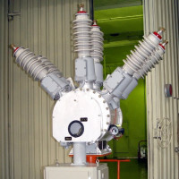 Gas-insulated switches: reference points and connection rules
 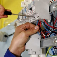 RCD for a water heater: selection criteria + schemes and connection rules
 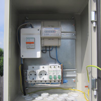 Box for electric machines: types of boxes and their features + the nuances of selecting and filling the box
 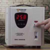 Rating of voltage stabilizers for the home: a popular ten among buyers + the nuances of choice
  How much does it cost to connect gas to a private house: the price of organizing gas supply
  The best washing machines with dryer: model rating and customer tips
  What is the color temperature of light and the nuances of choosing the temperature of the lamps to suit your needs
  Replacement of a geyser in an apartment: replacement paperwork + basic norms and requirements
Can I find out in more detail why such a grounding of the switch is necessary?
Good afternoon, Artem. The main purpose of such grounding is to guarantee the safety of work.
The first image is a fragment of an outdoor switchgear circuit. Depicted, it seems (letters are not clear), a vacuum circuit breaker and current transformers. The latter are technologically related to explosives. Such sections of switchgear must be “fenced” with stationary grounding knives, which guarantee the safety of the personnel repairing, servicing explosives, TTs, and other elements of the circuit section. These earthing switches are regulated by clause 4.2.28. PUE. Screenshot - attached.
The second image is a fragment of a 10 kV enclosed switchgear. The purpose of these knives is similar. Performing work, personnel isolate the work area with disconnectors (cuts off electricity from all sides of the possible erroneous supply of voltage), and connects the equipment that was removed for repair with ground with grounding knives.