Features of connecting automatic machines and RCDs in the shield: circuits + installation rules

The comfortable connection of all its inhabitants and the smooth operation of household appliances depend on the correct connection of the wiring in the house. Do you agree? To protect the equipment located in the house from the effects of overvoltage or short circuit, and the inhabitants from the dangers associated with electric current, it is necessary to include protective devices in the circuit.
In this case, it is necessary to fulfill the main requirement - the connection of RCDs and automatic devices in the shield should be done correctly. It is equally important not to be mistaken in choosing these devices. But don’t worry, we will tell you how to do it right.
In this article, we will talk about the parameters by which RCDs are selected. In addition, here you will find features, rules for connecting machines and RCDs, as well as many useful schemes for connecting. And the videos shown in the material will help to realize everything in practice even without the involvement of specialists, if you are even a little versed in electrics.
The content of the article:
Basic principles of connection
To connect an RCD, two conductors are needed in the shield. In the first of them, the current flows to the load, and in the second, it leaves the consumer along the external circuit.
As soon as a current leak occurs, a difference appears between its values at the input and output. When the result exceeds a predetermined value, RCD triggered in emergency mode, thereby protecting the entire apartment line.
Residual current circuit breakers are adversely affected by short circuit (short circuit) and voltage drops, so they themselves need to be covered. The problem is solved by including automata in the circuit.

The current supplying electrical appliances flows through one of the core windings in one direction. He has a different orientation in the second winding after passing through them.
The independent implementation of the installation of protection devices involves the use of circuits. Both modular RCDs and automatic devices for them are installed in the shield.
Before you begin installation, you need to solve the following issues:
- how many RCDs should be installed;
- where they should be in the circuit;
- how to connect, so that the RCD works correctly.
The wiring rule states that all connections in single phase network must enter the connected devices from top to bottom.
Professional electricians explain this by the fact that if you start them from below, then the efficiency of the vast majority of machines will decrease by a quarter. In addition, the master working in the switchboard will not have to further understand the scheme.
RCDs, designed for installation on separate lines and having low ratings, cannot be mounted in a common network. In case of non-compliance with this rule, the likelihood of leaks and short circuit will increase.
RCD selection by main parameters
All the technical nuances associated with the selection of RCDs are known only to professional installers. For this reason, specialists should make the selection of devices during the development of the project.
Criterion # 1. The nuances of selecting the device
When choosing an apparatus, the rated current passing through it in continuous operation is the main criterion.

The value of In is in the range of 6-125 A. The differential current IΔn is the second most important characteristic. This is a fixed value, after which an RCD is triggered. When it is selected from the range: 10, 30, 100, 300, 500 mA, 1 A, safety requirements have priority.
Affects the choice and purpose of the installation. To ensure safe operation of one device, they are guided by the value of the rated current with a small margin. If protection is needed for the house as a whole or for the apartment, all the loads are summarized.
Criterion # 2. Existing types of RCD
It is necessary to distinguish between RCDs and by types. There are only two of them - electromechanical and electronic. The main working unit of the first is a magnetic circuit with a winding. Its action is to compare the values of the current going to the network and returning back.
There is such a function in the apparatus of the second type, only its electronic board performs it. It works exclusively in the presence of voltage. Because of this, the electromechanical device protects better.

In a situation where the consumer accidentally touches the phase wire, and the board turns out to be de-energized, in the case of installing an electronic RCD, a person will get under voltage. In this case, the protective device will not work, and the electromechanical in such conditions will remain operational.
The subtleties of choosing an RCD are described in this stuff.
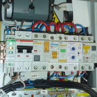
Installation of RCD and automatic devices in the shield
The switchboard, in which the metering and load balancing devices are located, is usually the place for the installation of RCDs. Regardless of the selected scheme, there are rules that are required when connecting.
General Connection Rules
Along with the automatic shutdown device, they are installed on the shield and automatic machines. All that is needed for this is a minimum of tools and a competent scheme.
The standard set should consist of:
- from a screwdriver package;
- pliers;
- side cutters;
- tester;
- socket wrenches;
- cambrica.
Also, installation requires a VVG cable of different colors, selected according to the cross-section in accordance with the currents. PVC insulating tube mark the conductors.
When there is room on the DIN block on the switchboard, a residual current circuit breaker is mounted on it. Otherwise, install additional.
The key installation principle is as follows: the contact of the neutral conductor after the RCD with either the input zero or grounding is unacceptable, therefore it is isolated by analogy with other wires.
In series with the RCD, it is necessary to turn on the circuit breaker. This is also one of the most important rules.
When the protection of the entire housing is performed using one RCD, a circuit is used that includes several machines.

In addition to additional AB, one more component is included in the project - the zero bus isolator. Mount it on the shield body or on a din rail.
This addition is introduced due to the fact that with a large number of neutral conductors connected to the output terminal of the disconnecting device, they simply do not fit in one terminal. An isolated zero bus is the best way out of this situation.
Sometimes, electricians, in order to put the entire bundle of zero wires in the socket, decide to file the wires of the single-core cable. In the case when a multi-core cable, several veins are removed.
This option is better not to use, because due to a decrease in the cross section of the conductors, the resistance will increase, therefore, the heating will increase.
Both the number of mounting holes and their diameter can be different. The ground bus is attached directly to the chassis.
Zero wires in one twist - an additional inconvenience when detecting damage on the line, as well as when you need to dismantle one of the cables. Here you can not do without unscrewing the clamp, unwinding the tourniquet, which will certainly provoke the appearance of cracks in the veins.
It is impossible to mount simultaneously and two wires in one socket. The inputs of the circuit breakers are connected by jumpers. As the latter, for professional installation, special connecting tires are used under the name “comb”.
Features of connection schemes
The choice of scheme involves taking into account the features of a particular electrical network. Among the numerous options, there are only two circuits used to connect machines and RCDs in visorconsidered basic.

In the first and simplest way, when one RCD protects the entire electrical network, there are disadvantages. The main one is difficulties in identifying a specific damage site.
The second is that when a failure occurs in the operation of the RCD, the entire system will be taken out of operation. A safety shutdown device is allocated a place immediately after the counter.
The next method involves the availability of such devices on each individual line. If one of them fails, all the others will be in working condition. To implement this scheme requires a larger overall shield and higher costs in financial terms.
In detail about a simple scheme
Consider connecting an RCD with automatic devices to a simple apartment shield. At the entrance there is a bipolar switch. A two-pole RCD is connected to it, to which two single-pole machines.
A load is connected to the output of each of them. In principle, RCDs are introduced into the circuit as well as circuit breaker.

The phase, brought to the automatic switch on, goes to the input of the RCD with the output to the machines. The zero output from the machine goes to the zero bus, and from it - to the entrance to the device.
From its output, the zero conductor is sent to the second zero bus. The presence of this second tire is a special nuance, without knowing about which it is impossible to achieve the normal functioning of the circuit.
The RCD during the operation monitors both the input and output voltage - how much input has entered, so much should be at the output.
If the equilibrium is violated and at the output it is greater by the value of the setpoint to which the RCD is configured, it is triggered and the power turns off automatically. The zero bus is responsible for this process.
In electrical circuits where the installation of a residual current device is not provided, only one common zero.
In the circuit with an RCD, the picture is different - there are already several such zeros here. When using one device, there are two of them - the common one and the one with respect to which the protective device works.
If two RCDs are connected, there are three zero buses. Denote them by indices: N1, N2, N3, etc. In general, there are always one more zeros than residual current devices. One of them is the main one, and all the rest are tied directly to the RCD.

If not all equipment is supposed to be connected via an RCD, then zero is supplied from the common bus. The residual current device in this case is excluded from the circuit.
When adding a single-pole circuit breaker operating from an RCD, from the output of the last phase, they are fed to the input of the circuit breaker. From the output of the switch, the conductor is connected to one load contact. Zero on it lead to the second conclusion. It comes from the zero bus created by the RCD.
There is another element on the shield - a protective grounding bus. Correct operation of an RCD is impossible without it.
A three-wire network is available only in new homes. It necessarily has a zero phase and grounding. In houses built for a long time, there is only phase and zero. Under such conditions, the RCD will also function, but in a slightly different way than in a three-phase network.
As a way out of the situation, grounding is displayed by the third conductor on the outlet, and then on the ceiling to the place where the chandeliers are connected. To the switches "ground" is not served.
Option to connect machines without an RCD
There are times when one of the machines needs to be connected, bypassing the protective shutdown device. The power is connected not from the output of the RCD, but from the entrance to it, i.e. directly from the machine. The phase is fed to the input, and from the output it is connected to the left terminal of the load.
Zero is taken from the common zero bus (N). If damage occurs in the area controlled by the RCD, it will be removed from the circuit, and the second load will not be de-energized.
RCD in a three-phase network
A network of this type includes either a special three-phase RCD with eight contacts, or three single-phase.

The connection principle is completely identical. Mount it according to the scheme. Phases A, B and C supply power to loads rated for 380 V. If we consider each phase separately, then in tandem with a cable N (0), it provides a series of single-phase consumers of 220 V.
Manufacturers produce three-phase trip protection devices adapted to high leakage currents. They protect the wiring only from fire.

In order to protect people from the effects of electric current, single-phase bipolar RCDs are installed on the outgoing branches, configured for a leakage current in the range of 10-30 mA. For cover, an automatic machine is inserted in front of each. In the circuit after the RCD, it is impossible to connect the working zero and ground.
RCD and machines on a three-phase switchboard
We will analyze in detail the not quite standard circuit assembled on a three-phase switchboard.
On it are:
- three-phase input circuit breakers - 3 pcs .;
- three-phase residual current device - 1 pc.;
- single-phase RCD - 2 pcs.;
- single-pole single-phase automatic machines - 4 pcs.
From the first input circuit breaker, voltage is supplied to the second three-phase circuit breaker through the upper terminals. From here, one phase goes to the first single-phase RCD, and the second to the next.

Single-phase RCDs installed on the shield are bipolar, and the machines are single-pole. For the protective device to function correctly, it is necessary that the working zeros after it do not connect anywhere else. Therefore, after each RCD, a zero bus is installed here.
When the machines are not single, but bipolar, then you do not have to install a separate zero bus. If the two zero buses are combined, a false positive will occur.
Each of the single-pole RCDs is designed for two machines (1-3, 2-4). The load is connected to the lower terminals of the machines.
The common ground bus is installed separately. Three phases enter the introductory machine: L1, L2, L3 and the working neutral wire.
Zero is connected to a common zero, and it goes to all RCDs. After that, it goes to the load: from the first device - to a three-phase, and from the following single-phase - each to its own bus.

Although the input is three-phase in this switchboard, the separation of the wire into PEN and PE has not been performed since five-wire input. Three phases come to the shield, zero and ground.
Conclusions and useful video on the topic
The nuances of installing all the elements on the dashboard:
Details of the installation of RCDs:
RCDs and automatic machines are technically sophisticated equipment. It is advisable to install it in places where electric current can pose a threat to both the safety of people and home appliances.
Its installation involves taking into account many parameters, so both calculation and installation are better performed by qualified specialists.
If you have experience in self-installation of RCDs, please share it with our readers. Tell us what points you should pay special attention to. Leave your comments, ask questions in the block under the article.
 Fire RCD: selection recommendations, rules and installation diagrams
 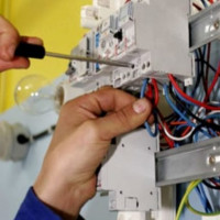 RCD for a water heater: selection criteria + schemes and connection rules
 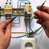 Rules for connecting an RCD to a single-phase network without grounding: the best schemes + operating procedure
  How to connect an RCD: circuits, connection options, safety rules
 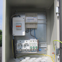 Box for electric machines: types of boxes and their features + the nuances of selecting and filling the box
  Bipolar and three-pole switches: purpose, characteristics, installation features
  How much does it cost to connect gas to a private house: the price of organizing gas supply
  The best washing machines with dryer: model rating and customer tips
  What is the color temperature of light and the nuances of choosing the temperature of the lamps to suit your needs
  Replacement of a geyser in an apartment: replacement paperwork + basic norms and requirements
In all the photos and figures here (and on other sites) the phase conductor passes through the left shoulder of the RCD (etc.), and “N” through the right. Whereas on the RCD of the company “DIN Electro Kraft”, Moscow, the letters “N” are brightly juicy on the left shoulder. What is more correct if you can ask a question like that?
And another question - on the RCD (etc.) it is often stamped “Remove the plug (or plug) for installing additional devices”. The stubs are clear what, but what devices and how they look - I have not seen. What kind?
Good afternoon, Boris.
Correct connection is guaranteed by the symbols printed near the terminals. If there are no characters, then you need to read the passport. For example, on a Schneider Electric RCD, the EASY 9 2P modification with a leakage current of 30 mA, zero is connected on the left, and on a TDM RCD, the VD63 model (nominal 16 A, leakage current 30 mA) on the right. Screenshots of these RCDs - attached.
On the second question, I can assume that the additional devices are, for example, complete buses that provide quick installation of machines connected under RCD. In the article, note that all photos contain wired wiring. A number of foreign manufacturers offer faster installation with tire kits. A screenshot of such a wiring - attached.
Where in nature there is generally a five-wire automatic machine about which you write ...
“The common ground bus is installed separately. Three phases enter the introductory machine: L1, L2, L3, the working neutral wire N and PE are protective. ” - There are none, there are only four wires: three phases and zero, ground, ne. PE, in English, the potential of eart, is never switched, otherwise it is not land.
Good afternoon, Victor.
Of course, five-wire circuit breakers do not exist. The proposal you highlighted should have ended with the words "working neutral wire." By the way, the image preceding this text is correct.
RCD during operation monitors both incoming and outgoing voltage ... - current, controls the leakage current.
A three-wire network is available only in new homes. It necessarily has a zero phase and grounding. In houses built for a long time, there is only phase and zero. Under such conditions, the RCD will also function, but in a slightly different way than in a three-phase network. Than in a three-wire meant.