Bipolar and three-pole switches: purpose, characteristics, installation features

The purpose of circuit breakers, which are implemented in electrical networks, relates to protective functions. If you use a handheld device in network congestion mode, the likelihood of significant damage to equipment increases significantly.
Automatic two-pole and three-pole circuit breakers reduce such risks to a minimum, as they provide instant open circuits in case of an accident.
We will understand the features of electric machines, give tips on the selection, installation and operation of such devices.
The content of the article:
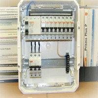
Design of circuit breakers
In the practice of using such equipment, three types of devices are often used: single-pole, two-pole, three-pole.
What is the difference between these three types of machines? Let's try to figure it out.

A single-pole device, in general, does not cause special problems. If you introduce single phase circuit breaker, then the device will work like a normal switch, only in the automatic reaction mode - that is, without user intervention, it will break the circuit in case of violation of the specified operating conditions.
Brief description of the bipolar
A similar device, but executed in the form of a two-pole circuit breaker, is slightly different in functionality.
The circuitry of a two-pole device is made taking into account the control and comparison of the working conditions of two independent current lines.

Bipolar automatic machines are used, as a rule, for implementation in projects of building electric networks, when it is necessary to monitor and compare the working conditions of two sections of a single electric network. In fact, the bipolar configuration of the device is a tandem of a pair of unipolar devices.
However, the two-terminal protection and blocking circuit works on the principle of comparing the parameters of each device individually, in real time. If the parameters go beyond the boundaries of the installations in either of the two control sections, both lines are instantly broken.
This important point shows: the replacement of a two-pole circuit breaker with a pair of ordinary single-pole devices is impossible in principle. In case of overload of one of the circuits (or short circuit), only one machine will work.

But given that the electric network is single, electricity will continue to flow through a second device that feeds another section. This situation leads to grave consequences.
Meanwhile, there are two subspecies of bipolar devices:
- with protection of one pole and normal neutral switching;
- with protection of both poles and their simultaneous switching.
The former are usually used as input machines, thanks to which the phase and neutral conductors are switched. At the same time, such a switching circuit provides for the use of an additional PE line - a grounding wire.

The second find application in the circuits of the same network, where two sections are fed, operating under different current loads.
Features of a three-terminal device
The main purpose of a three-pole circuit breaker is the use of three-phase networks in circuits. Design features of this type of devices are the presence of protective functions at each individual pole.
The operation of protection at any of the poles leads to the opening of all poles.

Despite the specific purpose of machines of this type, it is quite acceptable to use them on single-phase or two-phase lines.
Structurally, a three-pole machine contains the following elements:
- management mechanism;
- contact system;
- arc extinction module;
- trip device.
Loose contacts are usually mounted inside the instrument cover. The contact system communicates with the traverse of the main contacts in a kinematic way.
Functional components of the device are mounted inside the housing. The cover and body of the machine are made of materials that do not allow electric current (plastic, textolite, etc.).

The three-terminal protection mechanism provides momentary shutdown, both in the “auto” mode and in the case of manual operation. In this case, if there is an overload in the electrical circuit, a momentary shutdown occurs regardless of the force exerted on the control handle.
That is, even if the user keeps the handle in the on state, the machine will still open all poles in overload mode.
There are modifications to the three-terminal network, where another pole is added under the neutral conductor. In fact, we are talking about a four-pole design in terms of structural details.

Functionally, the four-pole machine resembles a two-pole system. The task of the device is the same, only with respect to a three-phase network.
Generalized technical characteristics of machines
Information on the main parameters of circuit breakers is indicated on its case. To understand alphanumeric characters, you must be able to “Read” device labeling.
Widespread in everyday life and industry are devices that meet the following main technical characteristics, depending on their design:
| Machine configuration | 1 pole | 2 pole | 3 pole |
| DC voltage, V | 240 | 440 | 600 |
| AC voltage, V | 380 | 380 | 660 |
| Rated current, A | 0,6 – 100 | 0,6 – 100 | 0,6 – 100 |
| Voltage of shunt trip, V | 24 – 440 | 24 – 440 | 24 – 440 |
| Norm of ambient temperature, ºС | -25 / +60 | -25 / +60 | -25 / +60 |
Devices are selected according to certain criteria, among which voltage, value of rated current, temperature indicators.
Read more about choosing circuit breakers in the articles:
- Choosing a circuit breaker: types and characteristics of automatic machines
- Machine selection by load power, cable cross-section and current: principles and formulas for calculations
Mounting subtleties of switches
For all electrical appliances of this design, the procedure for introducing into the electrical circuit is determined.

In accordance with the established procedure, in particular, the following actions of the installers are expected before the bipolar and three-pole switches are installed:
- the device must comply with the design for the current circuit;
- the machine case has no deformation and damage;
- the on / off lever clearly works in manual activation mode.
The base on which the device is supposed to be installed must be checked for evenness. Installation on the base is not allowed, where due to the uneven surface after fastening, the machine body is subjected to bending stresses.
Connection to network conductors
Connection of copper conductors having a cross section of 16 - 25 mm2perform through cable lugs (GOST 9688-82). If it is necessary to make a connection with conductors of copper with a cross section of 4 - 16 mm2other types of cable lugs are used (GOST 7386-80).
With regard to the connections of aluminum wires, end elements are used by analogy with TAM-7, corresponding to the parameters GOST 9581-80.

Network conductors supplying voltage from a power source are connected to the upper group of fixed contacts of circuit breakers. Conduct and connect the conductors so that they do not create forces on the terminals of the machine.
Tips should be tightened with contact clamps tightly, but without critical efforts that could lead to thread breakage.Sealing conductors in cable lugs should be given high attention. Be sure to use insulating tubes, tape as a protective sheath.
Nuances of arrangement and fixture
When you perform the installation of several pieces of equipment, you must follow the rules for the arrangement of devices relative to each other. So, the distance between closely spaced devices should be maintained at least 5 mm.

Minimum distances from the metal parts of the switchgear: from top 30 to 50 mm, from the side 5 to 10 mm, depending on the magnitude of the supplied voltage.
If instruments used are used that are structurally made in an additional shell, all mounting manipulations are performed with the shell cover removed. The installation of the cover is carried out taking into account the correct entry of the drive mechanism leash. Screw fastening of the cover is performed evenly.
Upon completion of installation, the machines must be checked for clarity of the on / off moment.
Circuit diagrams and circuit breaker connection rules are described in detail in this article.
Maintenance during operation
The normal operating conditions of bipolar and three-pole circuit breakers allow you to allocate time for technical inspection of devices no more than one prophylaxis in three years of operation. This fact once again confirms the high quality of performance of almost any automatic machines.

Meanwhile, according to the instructions, a technical inspection is necessarily carried out if the circuit breaker is tripped due to a short circuit current.
For any reason, whether the device is triggered in an emergency or scheduled maintenance, the technical inspection of the devices includes:
- diagnosing the on / off mechanism in manual mode without load;
- checking the tightness of the screws of the main and loose contacts;
- reliability of fixture of the device to the basis;
- cleaning from dirt and foreign objects;
- simulation of shutdown by the method of mechanical action on a sensitive element;
- performance check in operating mode.
The practice of using electric networks notes the handling of devices from different manufacturers, including domestic and foreign ones.
Most of the automatic protection devices in use are characterized by excellent quality performance.
Conclusions and useful video on the topic
What are machines and how they differ, you can find out from the following video:
About the selection criteria for protective devices:
The reliability of the automatic locking devices is often determined not by the brand, but by the correct selection taking into account the workload. Also, an accurate calculation of the cross section of conductors supplying the load from the machine and the calculation of the cross section of the input cable have a significant effect on the operation of the devices.
When all the nuances of installation are taken into account, even Chinese devices, which are several times cheaper than branded ones, work for a rather long period of time without any complaints.
Share with your readers your experience in connecting bipolar and tripolar switches. Please leave comments, ask questions about the topic of the article and participate in discussions - the feedback form is located below.
 Features of connecting automatic machines and RCDs in the shield: circuits + installation rules
 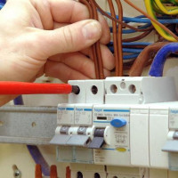 Differential circuit breaker: purpose, types, marking + selection tips
 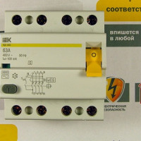 Selective RCD: device, purpose, scope + circuit and connection nuances
 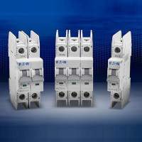 Choosing a circuit breaker: types and characteristics of automatic machines
  Gas-insulated switches: reference points and connection rules
  Box for electric machines: types of boxes and their features + the nuances of selecting and filling the box
  How much does it cost to connect gas to a private house: the price of organizing gas supply
  The best washing machines with dryer: model rating and customer tips
  What is the color temperature of light and the nuances of choosing the temperature of the lamps to suit your needs
  Replacement of a geyser in an apartment: replacement paperwork + basic norms and requirements