Connecting a chandelier to a double switch: schemes + installation rules

The chandelier not only complements the overall design of the room, but also serves as a light source in the dark. However, the maximum possible level of illumination is not used so often, right? For the most part, there is a need to use the economy mode, when only part of the lamps are functioning.
To this end, connect the chandelier to a double switch, which allows you to adjust the intensity of the lighting of the room. Do you want to install the switching device yourself, but don’t know how to do it right?
We will help you deal with all the nuances of this process - the article provides diagrams of connecting the device to a switch with two keys, addresses the basic errors that beginners make. Correct connection of wires will allow for control, providing comfortable lighting.
The material of the article is equipped with photographs, diagrams and recommendations in video format on the correct implementation of the connection of the chandelier on their own. Having studied the basic rules and installation diagrams, you can get to work.
The content of the article:
Safety comes first
Work with electrical wiring must be carried out in compliance with safety precautions and endurance of a clear sequence of actions.
First of all, the rules relate to de-energizing the wiring during the fitting process and wire strippingmounting the working mechanism of the switch, connecting the conductors to the terminals and other actions.

However, to determine the required wire, the presence of power supply is still needed, therefore, in work it is necessary to be as careful as possible and perform all actions only with special tools with high-quality insulation of the handles.

Installation of a double switch is carried out only in the gap of the phase conductor.
When inspecting the completed scheme, it is allowed to turn on and turn off lighting devices only after complete isolation of the bare wires and their final fixing.
The use of double switches
Connecting the chandelier to an electric circuit with a double switch allows you to use a group of lamps in turn as well as turn on a lighting device in all the power.
In this case, a two-phase device can operate by interacting with only two groups, the number of lamps in which is not limited.

Such adjustment fittings can be used in a private house, where the first line feeds outdoor lighting, and the second - a corridor, also in apartments, distributing power between the two rooms of the bathroom.
The two-gang switch is a pair of one-gang switches, completed in one case, therefore the connection diagram is almost identical.
To reproduce the installation plan, it is initially necessary to familiarize yourself with the design features of the product and with the elements connected to the mains.
Device with two keys
Modifications and types of light switches enough. However, the two-key electrical accessories gained popularity relatively recently, when lighting began to be reproduced using multi-tube chandeliers.
So there was a need for light distribution through zoning by spotlights.
No. 1 - model of self-clamping terminal block
The body of the device has standard parameters. Depending on the modification, it can be laid on or built-in, easily mounted on the external or internal part of the wall.
The second view is equipped with adjustable clips. Using the screws, the housing of the device is mounted in the desired position.

For fastening wires in modern hardware versions, plate clamps or a clamping plate with screws are used.
The screwless model is widespread and simply indispensable for self-installation for beginners. The wiring diagram and pin assignment are shown in most cases at the back of the case. Conventional marking values are also used.
The main designation is the Latin letter L, which means a contact for a phase wire. Nearby, a pair of arrows pointing down. They are interpreted as indicating the direction of the two outgoing phases. The numbers indicated at the place of the arrows carry the same meaning.

On the left side there are double contacts of the first switch key, on the right - the second.
Based on the connection method, each of the keys can provide voltage in different directions, for example, turn on several light bulbs of a lamp or illuminate a room located nearby.
For each of the conductors, its purpose is determined, so the best option is the use of a cable with wires of different colors.This will greatly simplify and speed up the wiring process.
No. 2 - connection of a screwless model
The process of connecting self-clamping contacts is much simpler in comparison with screw ones. First of all, they turn off the electricity supply. Further, all cores of the future contact should be cleaned from insulating material by 1 cm.
Each contact provides for the fixation of one pair of cores. The stripped wire is inserted all the way into the corresponding hole in the mechanism.
After turning on the electricity, you need to calculate the phase of the power. An indicator screwdriver is used for this purpose. After checking, the current supply must be cut off.

Following the diagram indicated on the back of the working part of the switch, it is necessary to alternately connect the multi-colored conductors, distributing them among the keys.
Consider a detailed action plan with a specific example.

In our example, the red supply phase is connected to the red wire that goes to the common contact of the on / off switch. At the exit from it, two wires are already obtained - burgundy and yellow.
The burgundy wire is directed into the junction box. There he connects to an identical color contact and goes to the first group of chandelier bulbs.
According to the scheme, the yellow phase contact going into the distributor must be connected to a wire of the same color that goes to the second group of fixtures.
The zero, shown in the diagram in blue and also coming from the electrical panel of the apartment, goes directly to the junction box, and then to the terminal block, where the zero of each of the group of chandelier lamps is connected.
Similarly to the zero vein, there is a yellow-green, responsible for the earth.

When installing and connecting a double switch, its working mechanism is hidden in the socket, locking in position with a screw mount. Next, the keys and decorative trim are placed on the device.
No. 3 - installation of screw contacts
In this case, there is no schematic indication. Visually, it is necessary to identify the two lower contacts, which, most likely, represent the outgoing phases, and the upper one - the supply phase.
You can verify the correctness of the actions by methodically turning the contacts on and off: when the keys are on, the circuit closes, in the off position, the circuit opens.

The mechanism of this type of switch is equipped with three screw contacts, through which the cores are connected, and two screws that drive the spacer legs.

For screw-type contacts, it is necessary to strip the cores by 0.5 cm. The cores are fixed by means of a plate, which is driven by screws.
Checking the correct connection of wires
The primary task is to inspect how correctly the switch was connected. On one of the lines, the voltage indicator in the open position should show the presence of the phase potential.
At the place where it is planned to install the chandelier, two wires must exit, namely the neutral and phase wire coming from the switch.
The number of conductors at the device itself will be more, especially when a multi-track lamp is connected. It is also possible that a grounding conductor is available if the house is wired with a TN-C-S grounding system.

For proper distribution of the purpose of each cable, it is necessary to check whether they have voltage. There are several special devices for this: indicator, voltmeter, digital multimeter, etc.
It is not difficult to work with the voltage indicator: it is necessary to touch its tip to the wiring section cleaned from insulation.
Only one cable does not illuminate the device - zero, the rest when it comes in contact with a screwdriver will cause it to glow - phase. Alternately switching the two keys of the switch will help to recognize that the wire belongs to the desired key.

A similar method of determination is used when measuring with a digital multimeter. It must be set in the "Volts" mode and set the scale - more than 220 V. Alternating, you must touch the probes to the pairs of wires.
Phase pair will not lead to changes on the instrument dial. By connecting the probes with a possible phase and zero, you can observe the figure 220 V. If the wiring has the same color, it is better to mark it with markers.
Decoding of the marking of electrical wires
For ease of identification and to avoid confusion, core insulation cable different colors. According to the standards, the ground wire is yellow with a green stripe.
Such a conductor is found in new buildings, where a high level of protection against electric shock is provided.

The neutral conductor is marked with an insulating sheath of blue or blue in which the core is enclosed. For the phase, any other shade variations other than those indicated may be applied.
Connection Options
The chandelier and other lighting devices are connected by crimping, soldering or through terminal adapters.
The first option involves the connection of conductor cores by crimping them with a retaining sleeve. The whole procedure is carried out with a special tool - press pliers. This method complies with all regulatory documents.
The second method is considered one of the most reliable, but difficult to reproduce. It is practically not used due to the inconvenience of working at height.

You can not twist aluminum and copper wires with each other - a galvanic pair is formed, which even with a slight increase in the level of humidity in the apartment can reproduce an electrochemical reaction in the form of oxidation.
This process breaks the contacts, and the docking point begins to heat up. It is for this reason that fires are formed.

Use is considered relevant. terminal block. At the moment, the range of this connecting element is quite wide - from the classic screw version to the spring version.
How to connect the chandelier?
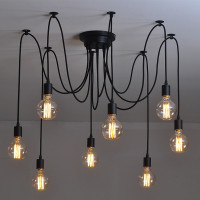
If you pay attention to the five-arm chandelier, in its arsenal there is a fairly large number of wires, so inexperienced craftsmen avoid such lighting devices.
However, there is nothing complicated in the process of connecting the wires going from the distributor to such a lamp.

First of all, you need to deal with the wiring on the ceiling, which in a standard situation has three wires:
- L1 - phase of the first switch button;
- L2 - phase of the second key;
- N - zero.
If the wires are the same in color, then using the voltage indicator determines the affiliation of each, i.e., phases L1 and L2. Accordingly, the remaining core will be zero.
Next, you can proceed to the process of forming contact nodes. Consider the example of a five-arm chandelier with 10 wires: brown phase wires - there are 5 of them, and the same number of blue ones is zero.

This lamp has one indisputable advantage - a combination of bulbs can be made up at your discretion. According to the scheme described below, the first group includes two bulbs, the second - the other three.

Based on this scheme, the five-arm lighting device is connected in several stages. Initially, a pair of brown wires is completed in one knot.
It is desirable that the lamps included in one series are connected in parallel. This twist is called L1.
The next step will be a similar twisting of the unused three brown wires. This will be the L2 series. Next, the resulting two nodes are inserted into two-wire terminal clamps Wago.

At the next stage, the blue cores are twisted and connected to a three-wire type terminal.
The connection order does not matter. The combination can be 3 + 2 or 2 + 3. It will be a neutral node - N.

As a result, the output yields 3 connection nodes: the phase of the first and second groups of lamps - L1 and L2, the common neutral node - N. Given the marking of the wires, they must be connected to the corresponding lines on the ceiling.

At the finishing stage, it is necessary to lay all the wiring in the block of the chandelier bowl and install it. Fastening is carried out in one of the ways: hung on a hook or screwed with screws. Next, the decorative plugs of the lamp are tightened.
Using ground wire
When arranging electrical communications in new homes according to generally accepted standards, a ground wire will be required in the wiring.
In such rooms, when installing the chandelier, you can find that 4 wires come out of the ceiling: two phases from the switch, zero and ground.

In most models of chandeliers with two groups of lamps and metal parts, a terminal block is provided in the configuration, through which the ground connection is made.
During the installation of the lighting device, you need to pay attention to this and connect the wire.
Halogen lamp connection
Chandeliers with halogen type lamps they do not always work from an AC voltage of 220 V - these can be products designed for an alternating voltage of 6, 12 or 24 V. Therefore, in the second case, a step-down transformer will be needed.
Sometimes the manufacturer in each model of a halogen lamp lighting fixture implements special transformers to reduce current.
At the same time, the circuit is already assembled and it remains only to install it. 2 cables remain unused, which are connected to the ceiling wiring, while the connection is arbitrary.

Chandeliers, which include a remote control, can be of various modifications: with halogen, LED or incandescent lamps.
There are models and a combined type. Such a device is complicated by the presence of a radio control unit. In fact, this controller is a wireless device, which is controlled by a remote control or a standard key switch.
The connection of such a lighting device is carried out similarly to the previous model, however, another wire will be added here, the thinnest of all.
This is the antenna through which the communicating actions of the console and controller are reproduced. It remains unchanged inside the glass of the chandelier.
Conclusions and useful video on the topic
The whole process of preparing the chandelier for connection and directly connecting to the power of the double switch is described in the video:
Inexperienced masters often make mistakes in the wiring process, which ones and how to avoid them, see the video:
If you reproduce correctly all the stages of installation and follow the diagram, you can protect yourself from unpleasant consequences during the direct operation of the lighting device. Moreover, it will be possible to create a unique lighting atmosphere in the room, adjusting it to fit your needs.
Share with your readers your experience of connecting a chandelier to a double switch. Please leave comments on the article, ask your questions and participate in discussions. The feedback form is located below.
 Assembly and installation of the chandelier: detailed instructions for installing and connecting with your own hands
  How to connect a chandelier to a two-gang switch: step-by-step instruction
  Lamp holder: device principle, types and connection rules
  Bulbs for suspended ceilings: rules for the selection and connection + layout of lamps on the ceiling
  Transformer for halogen lamps: why is it needed, the principle of operation and connection rules
 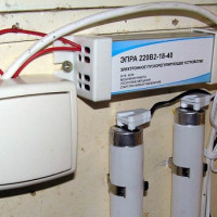 Electronic ballasts for fluorescent lamps: what it is, how it works, wiring diagrams for lamps with electronic ballasts
  How much does it cost to connect gas to a private house: the price of organizing gas supply
  The best washing machines with dryer: model rating and customer tips
  What is the color temperature of light and the nuances of choosing the temperature of the lamps to suit your needs
  Replacement of a geyser in an apartment: replacement paperwork + basic norms and requirements
If it is possible to choose a switch, it is better with backlight. We have everything in the apartment with them. But everyone’s style is different. Changed them gradually, a lot of low-quality devices on the market.You need to hold each in your hand, press the keys. If you feel sorry for the money, you can do the usual electrical tape instead of the terminals when connecting. True, it took a lot of time from her husband, and it didn’t work the first time.
I’m trying to connect a chandelier and there is a certain problem. There is a chandelier for 7 lamps and a double switch. The first switch should have 2 lamps and the second 5. Separately, everything works well, but if you turn it on together, then 5 lamps are on, not all 7. What could be wrong? Is it a malfunction of the chandelier or the switch, or is it still not enough straight hands of the electrician (me)?
The article, Andrey, describes in detail the connection of a chandelier via a two-gang switch. There is a scheme. If it’s complicated for you, look at the sketch that I attached to the post. My assumptions about how you mixed up the three wires will not help you.