TV outlet: how to install an outlet for a TV

Despite the regular updating of the market with new modifications of modern audio, video and TV equipment, there are traditional principles that ensure reliable signal transmission. One of them is the equipment of stationary sockets.
Here you will find out how the television outlet is mounted, in what sequence the point is connected. For independent masters, we thoroughly analyzed a number of important nuances. To optimize the perception of the material, we supplemented the information with diagrams, photo illustrations and video manuals.
The content of the article:
The subtleties of choosing a television outlet
Modern TV differs from its predecessors from the last century in its great capabilities and versatility. This is not just a video transmitter, but part of a multifunctional multimedia system.
It includes the broadcast of many domestic and foreign television channels, the ability to view photos and videos from mobile devices, access to the Internet, the use of game consoles.
With a huge load on the router, a wireless connection is not always reliable, so do not neglect the classic installation of an outlet for a TV.
The choice of modern, wall-mounted modules is quite extensive. We recommend paying attention to a series of brands such as Legrand, Schneider Electric, GIRA, IEK. They have a neat appearance, made of durable materials and do not cause installation difficulties.
Standard module device
The installation of television equipment has some differences from installation of conventional electric points and is considered separately, since the most important details - cable and sockets - also differ.
There are many options even for products from the same manufacturer (for example, Legrand produces the popular Valena, Celian, Etika, Galea Life series), but there are no fundamental differences in the device.
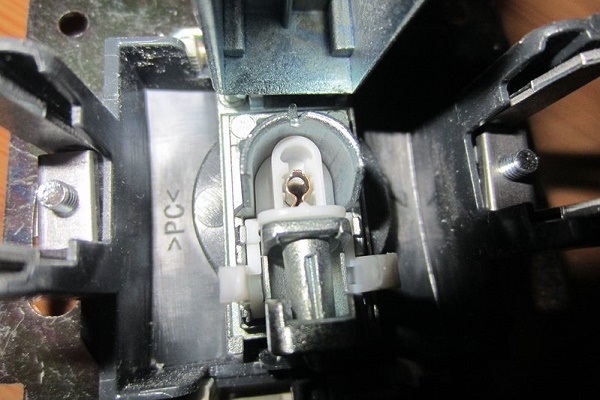
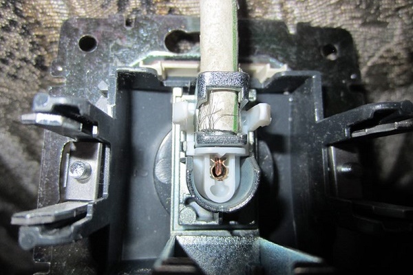
We will consider the structure of the outlet using the ABB Busch-Jaeger model as an example:

If we consider a sample from the Basic 55 series, then it consists of the following parts:

The structure of the printed circuit board may differ - for more complex modules, electronic circuits are located on it. On the back there is a mechanism responsible for fixing the antenna cable.
Types of sockets for the intended purpose
Before installing electrical equipment, you need to decide on the choice of sockets for the TV on the wall.
To make it easier to navigate in various modifications, manufacturers identified three main types:
- simple (single);
- walk-through;
- terminal.
The functional focus is in the names of categories, each of them has its own characteristics.
For example, to create the simplest circuit, in which one single module appears, acting independently, you need a simple socket. It is fundamentally different from the terminal, so when buying, require a product of the specified type.

Simply put, if you have one TV in your room with one cable connected, then this is your only option. If you install several TVs in the apartment, but use a standard splitter, then simple sockets can also come in handy.
The structure of the passage socket differs radically. It rather resembles a tee with 1 input and 2 parallel outputs.
One output is for connecting a video device, and the second is for a cable that goes further (or to the next TV, or to another power outlet). The chain of feed-through modules always ends with the installation of a terminal type socket.
There is a danger of signal weakening when compiling chains of a large number of modules through passage. To maintain sufficient power, we recommend limiting to 3-4 pieces.

The purpose of the terminal socket is to close the loop-through circuit.
Minimal set for the living room
Previously, when installing the TV, in addition to the power supply, nothing was required, since the antenna was connected directly to the receiver and installed side by side or, to receive a more powerful signal, was output outside, onto the roof or onto the balcony.
Now one electrical outlet little, since there are various standards for data transmission (digital and analog), which require their own connection.
Instead of 1 outlet, an entire unit consisting of at least 4 pieces is installed.

We recommend installing a block module for aesthetic reasons. If you initially had only an electrical outlet, and then a separate television outlet appeared next to it, with an Internet input, it will look extremely messy, scattered, and the place will most likely be in sight.If you plan to repair, be sure to start it with the wiring and installation of new equipment.
Two electrical outlets are also a minimum: one is for a TV, the second is for a digital set-top box or other equipment, which is often connected to modern video players. The TV module provides communication with cable television or an antenna brought out.
In addition, the antenna output is always a fallback. Suppose a digital set-top box is out of order or maintenance is being carried out somewhere - thanks to the antenna cable, you always have the opportunity to watch a free package of standard TV channels.

The Internet input is designed to connect a digital set-top box or signal supplied by the provider in a centralized mode. A twisted pair cable is connected to it from the router (and not from the common shield), which distributes a signal throughout the apartment.
The difference of the antenna cable
For a high-quality connection, in addition to correctly selected outlets, you will need an antenna coaxial cable, which has a special structure. Unlike a 2- or 3-wire electrical wire, it has one core for transmitting a television signal and a protective shield that serves as a barrier to the surrounding electromagnetic fields.
Externally, the television cable is a thick elastic wire of circular cross section, usually with PVC insulation in black or white. For wall mounting, the color of the outer insulation does not matter.

A thin insulating layer adjacent to the central core breaks the galvanic connection with the shielding braid.
The screen, in turn, protects against electromagnetic interference and prevents the emission of a sensitive high-frequency signal, being also an additional conductor. If any of the components fails, the video transmission will be disrupted.
Here are some types of cables that are suitable for laying under plaster or other finishing material:
- SAT 50 (SAT 703);
- RG-6 (and for external use);
- RG-11 (F1160BVM COMMSCOPE).
When buying, be sure to check the strength of the sheath, and during the packaging process and during transportation, try not to bend the cable so as not to violate the integrity of the copper core and the screen braid.
Connection schemes options
There are two main connection schemes - parallel ("star") and serial ("loop" or loop-through). All the others, no matter how complicated and intricate they are, are combinations of these two main options. They resemble standard electrical circuitsbut differ in less voltage.
# 1: “Star” - several independent lines
Once they used one video receiver for the whole apartment, now almost every room has televisions. To connect all devices to a single cable leading from a shield or aerial antenna, a special signal distribution device is required - a splitter or splitter.
This is a kind of switching organizer, having one input for an antenna cable and several outputs - for connecting TVs.

Advantages of parallel connection are not only in good signal quality, which is usually attenuated by power sockets. When mounting, the splitter is mounted in the most convenient place (for example, in the corridor), and it is easier to branch into other rooms from it.If one of the process cables becomes unusable, the functionality of the rest of the network will not be affected.
There is an improved solution to the “star” circuit with an amplifier that guarantees minimization of the attenuation of the video signal. The standard power supply is designed for 2-3 receivers, but usually there are more, so the amplifier compensates for the deficiency and ultimately improves the video signal.

For parallel connection, either terminal or simple sockets are required. Terminal ones are best preferred to avoid interference if one of the TVs is not actively used. They differ from simple ones by the presence of wave resistance (75 Ohm), which is able to balance the signal.
# 2: "Loop" - loop through serial circuit
Pass-through scheme is considered cheaper, but less quality. It was actively used in previous years, but modern digital technologies supplanted it, since they are able to work only through parallel connection.
It turns out that you can use a “loopback” connection only in the only case - if you have exclusively analog television and no changes are expected in the near future.

Pass-through modules are equipped with filters that muffle the reflected TV signal. The absence of a filter is easily determined by the characteristic ripples on the TV screen. When choosing products, pay attention to such characteristics as pass attenuation (from 1.5 to 5 dB) and branch attenuation (from 10 to 15 dB), give preference to devices with the smallest parameters.
Note that with an increase in the number of connections, the signal quality weakens even if the network is provided with an amplifier or an auto-regulation system, therefore it is better to use a parallel circuit for 4-5 or more receivers.
And carefully read the contract with the provider: in some cases they limit the number of active points, and impose a fine for installing additional ones.
Optimum height
If you decide to place the TV on the wall, the installation height of the outlet block is automatically determined - it is hidden behind the TV panel. The solution is different from standard placement options. conventional power points. This method of installing TV outlets is designed to completely mask the inlets, connectors, visible cable sections.
The wires hanging on the wall can spoil the design of the most sophisticated interior, in addition, their open location is a risk of breakage (small children will cut, the dog will gnaw, etc.).

The height of the installation of sockets is oriented to the height of suspension of the TV, which may vary slightly. Typically, television and video equipment is placed at eye level of a person sitting on a chair or sofa. The optimal distance is considered to be 1.2-1.4 m (from the floor surface to the center of the outlet). In relation to the TV - slightly below its upper edge.
But there are exceptions. For example, a kitchen video device is most often mounted a little higher, in free space, respectively, and sockets should be installed above a specified height.
The procedure for installing a simple TV outlet
Before installing the outlet, you must run the cable (for a simple single - the only cable leading from the switchgear). It is masked either in a closed way - under the plaster (drywall, decorative panel), or open - on the surface of the wall, in the cable channel. For the second option, external (overhead) sockets are required.
For the sample we take a quality product of the French manufacturer.

Before installing with a drill with a round nozzle, it is necessary to cut a hole and insert a plastic box (socket box). A cable about 15 cm long should come out of the hole.

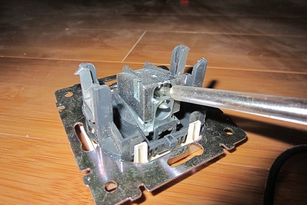
Next, we disassemble the product body into parts.

We insert the cable in the direction of the arrow and fix it with a special clamp, tightening the screw.

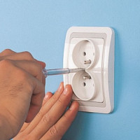
Testing by the tester will exclude the occurrence of a short circuit due to the accidental contact of the braid with the conductor.

The result of assembly and installation - no protruding wires and unprotected connectors.

The mounting of the feed-through module will be slightly different.
Features of parallel and loop-through circuitry
If you are not limited to installing an outlet for one TV and want to use the "star" scheme, pay attention to the following nuances:
- First of all, we mount the splitter, and only then - sockets.
- To each output of the splitter we attach one cable, which must end with the installation of one outlet (simple or terminal).
- When installing simple modules, please note that they are not equipped with filters.
Watch the frequency. According to GOST (R 52023), the possible frequency should fit into the framework from 40 to 1000 MHz, and some devices “narrow” these boundaries. For example, the operating range of DOCSIS v.2.0 is from 47 to 862 MHz, respectively, sockets support these restrictions.

If you are not interested in digital television and you have chosen a serial connection scheme, do not forget about the quantitative limitation.
The more outlets - the weaker the signal.From the level allowed by the Russian State Standard in the level of 57-83 dB, when 3-4 pieces are installed, you will exhaust the released limit (about 15 dB for each socket).
With the specifics of installation and connecting a computer outlet The following article will familiarize you with the contents of which we recommend that you familiarize yourself.
Conclusions and useful video on the topic
How to choose and install modern antenna sockets, you can see in the following videos.
Video # 1. Connecting the cable to a simple TV outlet:
Video # 2. Installing the Legrand power outlet:
Video # 3. Features of sockets of the German brand WISI:
For self-installation of an integrated television outlet, you must have the knowledge of an amateur electrician and be able to understand the types of wires and sockets. If you designed a complex circuit using additional devices, then for installation questions, it is better to contact the provider - only a specialist will be able to take into account all the nuances of the connection.
If you have any questions while reading the information, there are recommendations to help independent home masters, if you find any flaws in the material, please leave comments in the block below the article.
 How to connect a double outlet: installing a double outlet in one socket
 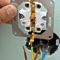 How to make two from one outlet and how to properly conduct an outlet from an outlet
 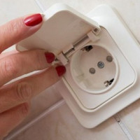 Installing a socket for a washing machine in the bathroom: an overview of the technology of work
 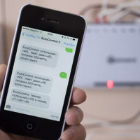 SMS socket: how a GSM-controlled socket works and is installed
 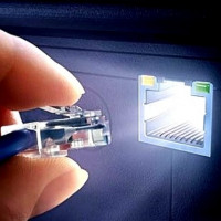 Computer outlet: types, categories, location rules and connection technology
 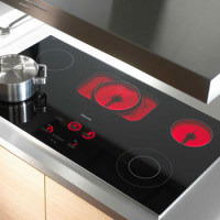 Power socket for electric stove: types, device, technical standards and rules for connection
  How much does it cost to connect gas to a private house: the price of organizing gas supply
  The best washing machines with dryer: model rating and customer tips
  What is the color temperature of light and the nuances of choosing the temperature of the lamps to suit your needs
  Replacement of a geyser in an apartment: replacement paperwork + basic norms and requirements
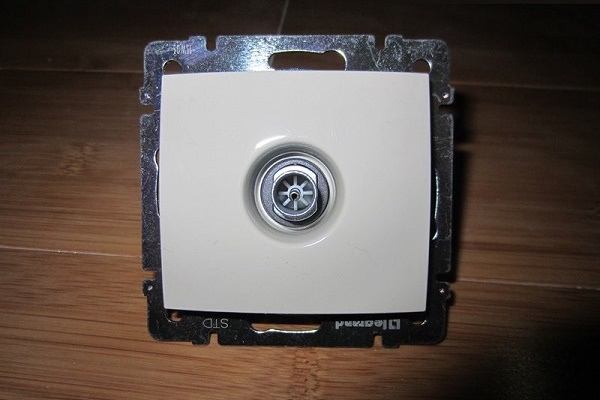
Recently I set myself such a TV outlet. When I bought it in a store, I wondered if I could install and connect it myself? I read a lot of reviews, watched video reviews with instructions. And thanks to all this information from the Internet, I installed a television outlet in my apartment without any problems. I believe that this solution is very convenient and adds an aesthetic look. I am glad that all the extra wires are hidden.
Probably, now, due to the implementation of the federal project to create a digital television broadcasting network, sockets for antennas are experiencing a rebirth. By the way, I know many who generally removed them from the apartment and have now spent it again, since it’s quite pleasant to watch twenty channels in digital quality for free. I want to give advice: when installing the outlet itself, it is worth paying attention to the fact that you do not need to jointly lay the electric cable with the cable from the antenna.
At first, there was a desire to hold such a power outlet, but then I figured it out, you need to ditch it, lay the cable, then it should all be covered up, aligned. It’s easier for me to run the cable through the cable channel under the TV itself, and let it go above the baseboard. Now, if my walls were covered with plasterboard, you can still strain, and with concrete walls there is more trouble.