Connecting the passage switch from two and three places: analysis of circuits + installation instruction

Switching light sources according to the principle of "approached, turned on - passed, turned off" - this is one of the options for the efficient use of electric energy. The functionality of such a control system is provided by the same traditional devices - switches, but structurally somewhat modernized.
Switching modernization allows you to connect the passage switch from two and three places to control the light source from each individual point. You must admit that such a solution is especially convenient for long rooms, for example, a corridor.
We offer you to understand the principles of connecting a passage switch to two and three control points. The article provides working schemes for organizing light groups, and also describes the features of the implementation of switching projects.
The content of the article:
Loop-through switching of light sources
The logic of saving energy spent on light devices or others is explained by simple user actions.
If a light fixture is needed, electricity is supplied to it by simply closing the contact of the switch. Otherwise, the opposite is true.

However, suppose the room (residential or other purpose) is walk-through. Then the user will turn on the light devices at the entrance, but leaving the room through another door, will no longer be able to disconnect the circuit. There is an irrational use of electricity.
But the situation is easy to correct. And the connection option will help to do this. passage switch from two places in the room for the loop-through scheme.

For example, there is a room with a functional purpose - a corridor. It is required to manage a common group of fixtures of this room from two points - at the first (entrance) and at the second (entrance) door.
Light switching from two places
The lighting of the project corridor consists of two light groups, therefore it is logical in this case to use two two-gang switches for control.
Accordingly, in addition to them, you will need:
- two socket boxes;
- one junction box;
- three-core cable.
The meter of electrical conductors should be calculated after drawing up the circuit and planning the wiring. It is recommended that you purchase a cable with a small margin.
The control circuit for two light groups through two-gang switches through passage looks like this:

The phase conductor is fed to the two-gang device PV1. This switch, having a two-key configuration, respectively, has two terminals for common contacts and four terminals for changeover contacts.
On the first device, the common terminals are connected together and a phase conductor is connected to them. The terminal 1 of the changeover contact PV1 is connected by a wire to the terminal 1 of the changeover contact PV2. Accordingly, terminal 2 of PV1 will be connected to terminal 2 of PV2, terminal 3 of PV1 with terminal 3 of PV2, and terminal 4 of PV1 with terminal 4 of PV2.
Two more terminals remain on the second loop-through switch. Both are common, and they are connected according to the principle: each into one light group (L1 and L2) of the lighting system. Already from light groups by outgoing conductors, the circuit closes to the zero bus of the electric network.
However, this is only one of the possible circuit solutions. So, if one light group is used, it is possible to organize a circuit on single-key switches.
Wiring using single-key walk-through switches looks more economical in terms of material consumption. Less wire is required here, since the number of connecting lines is reduced by almost half compared to the previous solution.
But at the same time, the functionality of the lighting system itself is limited.

However, for a device in residential premises, this option can be used most often.
What is required for a control system device on single-key switches?
The answer is obvious:
- single-key switches (2 pcs.);
- Sockets (2 pcs.);
- junction box (1 pc.);
- electric cable three-core (meter by calculation).
System requirements are standard. Before the start of work, a scheme is drawn up. Necessary accessories, materials, fasteners are purchased. According to designated places set the sockets and distribution box.

Then the cable is routed and the passage switches from two places are connected to the light source through the junction box.
Phase conductor lead to the common terminal PV2, and the common terminal PV1 lead to one contact of the light group. The second contact of the light group is connected to the zero bus, and the change-over contacts of both switches commute with each other, observing the same numbering (1 with 1, 2 with 2).
Three point management solution
The organization of loop switching systems is largely determined by the area of the premises (length), the number of moves (doors). Therefore, it is not ruled out the use of circuits with passage switches from three control points or more.
The construction of such schemes is usually carried out with the participation of the so-called cross switch.
This is the same switch, but according to the circuit design is made on five contact terminals, two of which are shorted by a jumper. The switching group of such a switch contains four pads.

The cross-line switching device is an additional element of the circuit, where it is also supposed to install two walk-through switches.
Simple single-key devices are used.
The principle of operation of the triple scheme is as follows:
- A phase is connected to the “common” terminal of PV1.
- From the terminals of the changeover contacts, 1 and 2 contacts of the crossover switch are connected.
- From 3 and 4 terminals of the cross-over switch, connection to 1 and 2 terminals of the change-over contacts of PV2.
- The common terminal “common” PV2 is connected to one terminal of the light group.
- The second terminal of the light group is switched to electric zero.
Such solutions involving just simple single-key devices are recommended for use in rooms where the number of inputs / outputs is equal to the number of control places.

For example, to create a similar scheme under the conditions of the passage of a long corridor, at 1 input and 1 output, with switching in the central zone, is clearly impractical. Obviously, it makes no sense to turn off the lights when a person has passed only the first half of the corridor. Meanwhile, in the network you can find similar recommendations of "professional" electricians.
Schemes with control from more than three places
The number of control places, in principle, is not limited. Another question is how difficult such decisions are. The more devices involved in the implementation of the control system, the more complicated the construction scheme.
The number of switched lines, contact terminals is increasing. Accordingly, the cost of components and installation increases. However, projects with 4-5 control points are used quite actively. For example, such a project:

It uses a pair of single-key simple switches of continuous operation and a pair of switches with a reverse switching function. The diagram shows only one light group. Meanwhile, it is possible to connect additional light groups.
Additional light groups
Additional light sources (light groups) can be switched off by free terminals and act as light sources of intermediate transition zones. That is, in the same long corridors, it becomes possible to use the scheme for a larger number of control places.

In this case, light groups should be divided into zones of action - input, intermediate, output. With this decision, it is already possible to pass a long corridor halfway, turn off the lighting on the passed half, and turn on the light on the section of the remaining half.
Multi-element schemes, of course, are of little use for a residential private sector, since projects of this kind rarely have long corridors or rooms of significant area with several doors. But for the commercial sector or the production environment, solutions of this kind are in demand.
Control system principles
Mounting features for installing walk-through switches, in general, do not exist.All installation work is carried out as standard, in accordance with the rules for installing conventional switching devices.

If the budget allows, it is advisable to equip each individual device with a junction box. Then you need to purchase boxes of small size by the number of mounted switches. But the option with one RK is also not excluded.
The selection factors here are directly related to the specific installation conditions. Typically, switches flush the wall surface — an internal wiring diagram.
Meanwhile, the implementation of projects for private estates (suburban) often takes place with the installation of schemes of "overhead" (surface) installation, despite the fact that this approach is considered to be obsolete.
For the first case, installation will require socket boxes. For the second - overhead plates. These accessories are necessary to securely fasten the switches in the niches of the wall panels or directly on the walls.

Three-core cables, as a rule, act as an electrical conductor, where two conductors are needed to power the system, and the third is used as a protective grounding circuit.
Household fixtures can be used without “ground” if the case is non-metallic. Industrial lamps must have a grounding bar.
Of course, regardless of the destination, domestic or industrial, the mounted network is always connected through additional protection - circuit breaker. This device is necessarily calculated by the power and cutoff current in relation to the built-in system of continuous light control.
Features of connecting a two-gang switch through passage are described in this article.
Conclusions and useful video on the topic
You can find out how the use of circuits for connecting breakers from several places can be found in the videos presented.
The procedure for connecting the cores in the junction box
Instructions for connecting from 2 places:
Analysis of possible errors:
The appearance and implementation of devices of this kind in electrical networks may not be so significant, but still affected the ease of use. Moreover, solutions based on break-through switches really lead to energy savings.
Meanwhile, the improvement of devices does not stop. New developments periodically appear, for example, similar to touch switches.
Is there anything to supplement, or have questions about connecting a pass-through switch? You can leave comments on the publication, participate in discussions and share your own experience in arranging the power grid. The contact form is located in the lower block.
 How to connect a passage switch: circuit analysis + step-by-step connection instructions
  Connecting a double switch: standards and diagrams + installation instruction
 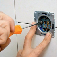 Wiring diagram for a two-gang switch and a step-by-step guide to installing it
 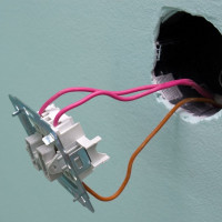 Connecting a light switch with two keys: the nuances of installation work
  How to connect a dimmer: possible schemes + instructions for connecting with your own hands
  Types and types of light switches: an overview of connection options + analysis of popular brands
  How much does it cost to connect gas to a private house: the price of organizing gas supply
  The best washing machines with dryer: model rating and customer tips
  What is the color temperature of light and the nuances of choosing the temperature of the lamps to suit your needs
  Replacement of a geyser in an apartment: replacement paperwork + basic norms and requirements
This is a pretty convenient feature, which can sometimes save electricity.In my house, I also have a passage switch with two places. The idea was given by a familiar electrician: I liked it, I decided to implement it. I did with the help of the same friend. Focusing solely on theory, it’s difficult to do everything, but in practice we had no problems, we installed everything quickly enough.