Cross circuit breaker: purpose and device + wiring diagram and installation

An electrical cross-over switch is a device designed for use as part of electrical communications circuits. In particular, this class of devices is actively used when it becomes necessary to organize control of light sources from different points. As a rule, the scheme involves the introduction of this device as an additional component to the existing pass-through switches.
In this article, we consider the design and electrical circuit of the device itself, as well as the connection features in various versions. We will supplement the material with visual diagrams, a photo and a video on self-assembly.
The content of the article:
Cross circuit breaker design
The device itself, the inverse switching of power lines is simple. However, due to the multi-point circuitry characteristic of such devices, implementation difficulties can become real. Therefore, it is logical to consider the design of the device, as well as the connection diagram.
The purpose of the communicator is obvious - the connection of electrical circuits for domestic (commercial) purposes, where the voltage level does not exceed 250 volts. The standard version of the devices is designed for operation inside dry, warm rooms, suitable for the established standard of protection class (IP20).

The installation of cross switches is carried out in the traditional way (similarly mounting a conventional switch light) with the mounting box mounted on screws, or internal mounting is done with the base fixed to the wall with metal tabs.
The body of the device is usually made on the basis of shock-resistant non-combustible technopolymer. All structural parts for outdoor installation are resistant to ultraviolet radiation.

The mechanics of cross-switches for current 10A are equipped with quick-clamping contact groups. Instrument mechanics for current 16A has screw terminals. For ease of connection, the terminals (phase and zero) are usually marked with a different color.
The terminals of the switches are designed for connecting conductors made using single-core or multi-core pull technology. Single conductor cross section up to 2.5 mm2stranded up to 4 mm2 (for 16A switches).
The electrical circuit of the device
If we consider the circuitry of cross-switching devices, it should be noted that there are different designs of devices in terms of the number of contact groups. Simple and frequently used devices (single-key) have 2 floating (moving) contacts and 4 stable (fixed) contacts.

A more complex design of cross-circuit breakers (two-three-key designs) is already marked by the number of communication groups of up to 4-6 movable and up to 8-12 fixed contacts.
A distinctive feature of this type of devices is their "dependent" installation. In other words, cross-functional circuit breaker designs are not installed without a pair of conventional switches.
That is why, choosing an intermediate action device, you should pay attention to the number of working contacts. For intermediate switches, the number of working terminals is always at least four.

Thanks to the use of such devices, it becomes possible to create more flexible and convenient operating schemes for controlling light devices. Particularly relevant is the practice of using cross-devices in the infrastructure of industrial enterprises.
Analysis of the schematic of the contact groups of the device
If you take the classic (single-key) design of the device manufactured, for example, by ABB, and deploy it to the user with the back side, approximately the following picture will open.
There are 4 pairs of terminals on the base board, each of which is marked with the corresponding symbols - in this case, “arrows”. By a technical designation of this kind, the manufacturer gives the user information about the correct connection of the device.

Incoming “arrows” indicate the general (cross over) contact group. Outgoing “arrows” mark a permanent contact group.
Schematically, the interaction of the groups looks like the following figure:

Conductors from the first come to the terminals of the general (cross over) group of the contactor passage switchinvolved in the electrical circuit. Accordingly, from the terminals of the second (permanent) group of the contactor, conductors come out that connect to the through switch number two, also prudently included in the circuit.
This is a classic variation using two walk-through and one reversing devices.

A device designed to play the role of a reversing switch can actually be used in one of two modes of switching an electric circuit:
- Direct switching - An analogue of two devices through passage.
- Cross switching - main destination.
The configuration of the first option, in fact, is represented by the functionality of a direct connection with the possibility of communication or disconnection.
The second configuration method (by setting jumpers) puts the device into operation according to the inversion switching scheme.

Thus, the intermediate switches look functionally not just as switches of artificial light sources, but as universal switches. This factor expands the functionality of such devices, making them convenient for use in various installation options.
Mounting features and circuit connection
Mount inverted switches using standard methods and methods used in construction or in the electrical industry. Convenient location of the device is preliminary planned.
Then, taking into account the selected mounting point and binding to the general electrical circuit, draw a wiring diagram for the intermediate switch and working with it in a pair of walk-through switches.
As part of the project development procedure, the method of laying conductors is determined - surface or internal.

Taking into account the chosen method, the installation infrastructure is prepared (strobes, holes, mounting plugs, junction boxes).
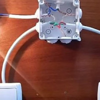
On the finished infrastructure, electrical wiring lines are pulled, wires are routed in the distribution boxes, the ends are routed directly to the connection to the through and intermediate switching devices.
Option # 1 - the nuances of connecting an intermediate device
The ends of the conductors withdrawn from the junction box for connection with an intermediate switch (4 in total) must be prepared. In particular, insulation is removed in the section from the end along the wire, approximately 10-12 mm long.
By the way, many branded circuit breakers have a special marker on the chassis, by which it is easy to measure the required length of the insulation stripping.

Now it is necessary to identify two conductors emanating from the first passage switch installed in the circuit. Typically, all conductors are marked for ease of identification even at the stage of wiring the circuits.
These two wires are connected at two input terminals (in this case, spring type) of the intermediate switching device. The remaining two are wired to the output terminals.

The chassis prepared in this way needs to be put in place - installed inside building socket (for internal installation) or fix directly to the wall surface (external surface-mounted installation).

Under conditions of internal installation, the chassis is usually fixed with spacer brackets or direct screw fasteners. With overhead mounting of switches, direct screw mounting is traditionally used. Further, a frame is placed on the chassis and a cover key is put on the control lever of the switch.
Option # 2 - circuit solutions for several devices
Intermediate installation switches are an integral part of circuit solutions, where the principle of control from more than three points remote from one another is implemented.
Theoretically, there can be many such control points for artificial light sources. However, options for three or four, with a maximum of five positions, are practically being implemented. Since with each new input of the device the general wiring diagram is complicated.

For an example, we can consider a four-position wiring when two pass-through and two reversing switching devices are used from the main components. In such a scheme phase wire fail on the movable contact of the through switch.
When a current is supplied to the network, it passes through the closed contact group of the loop-through device and is supplied to the movable contact of one of the two cross-over switches.
Further, from the output terminal of the reversing device, the current flows to the second switch of the same type - to its movable contact group and through the output terminal it enters the permanent contactor of the second pass-through switch.
If the cross over switch of this switch closes the circuit, from its output current flows to the light device. Through the filament of the lamp the common circuit is closed on the zero bus. Lamps are on. Now, if for the sake of experiment (and in practice, too) one by one to set any of the devices to the “off” state, the lamp lamps will go out in each of the four cases.

But if you turn off all four at the same time, this peculiar communication group will simply switch to another switching line and the lamp lamps will remain energized - they will continue to burn.
The experiment with reversing devices clearly shows the functionality of the cross four-position switch circuit. In any of the four positions, control of the light device is available.
Conclusions and useful video on the topic
Video on the practice of controlling light fixtures using a cross switch.
How to install and separate the line of wires from the passage switches to the cross and how to connect the devices:
The advantages of using PV are obvious, both from the point of view of user convenience and in terms of energy savings. That is why the considered electrical appliances are rapidly gaining popularity both in everyday life and in the industrial and economic sphere.
Do you want to supplement the above material with useful comments, wiring diagrams or installation recommendations? Or maybe you noticed inaccuracies or inconsistencies in this article? Please write your comments and tips in the comments section.
 How to choose a passage switch: device and purpose of various types + marking
 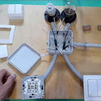 Two-way walk-through switch: device + wiring diagram + installation tips
  Load breaker: purpose, device, features of selection and installation
 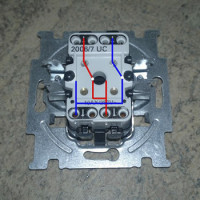 Rocker switch: marking, types, connection features
  How to install a light switch: step-by-step instructions for connecting typical switches
  How to connect a passage switch: circuit analysis + step-by-step connection instructions
  How much does it cost to connect gas to a private house: the price of organizing gas supply
  The best washing machines with dryer: model rating and customer tips
  What is the color temperature of light and the nuances of choosing the temperature of the lamps to suit your needs
  Replacement of a geyser in an apartment: replacement paperwork + basic norms and requirements
When we did the interior decoration of the house, the craftsmen suggested that we install cross and walk-through switches - to turn on the light simultaneously on the stairwells of all floors. It turned out to be very convenient. Outwardly, such a switch is no different from a conventional one, so our guests are very surprised when the lights on all floors light up. Still, few people know about such a chip.
The electrician, who changed my wiring during the overhaul, suggested making break-through switches in the hallway, I agreed. But when another team of craftsmen arrived, they mixed up the wires connecting the switches on both ends. Now these switches work for me according to a strange algorithm, which I still can’t understand: the light at the beginning of the corridor turns on only if the switch position at the end of the corridor is on, and if you switch to the off position, the light in the hallway is off at all. We'll have to redo everything, unfortunately. Cross-over and pass-through are different concepts or not?
Surprisingly, the team of “masters” did not check the operability of the network into which they climbed.
The cross (intermediate) switch and the passage switch are not the same thing. These switches have different connection schemes.
Good afternoon, Eugene. Cross and walk-throughs have different “internal circuits”. In the article, by the way, the diagrams are given - I attached my screenshots for you. Of course, you have to redo it. I advise you to think about the introduction of motion sensors, which will eliminate the need for ditching tracks for new wiring. On this site, the topic of sensors is covered in several articles. You can start with the material “How to connect a motion sensor to a light bulb”.