How to connect a telephone socket: connection diagram and installation rules

Despite the rapid decline in the popularity of stationary telephones, there are not so many people who are ready to refuse them outright. Admit it, it happens that without a traditional connection it is sometimes extremely difficult or even impossible to do.
To connect the device to the switching network, a low-current node is needed, the installation of which can be handled personally. We will tell you in detail how to connect a telephone jack without calling a wizard.
There is absolutely nothing complicated in the schemes and methods, and the useful information that we proposed, as well as photos and videos, will help to deal with the issue.
The content of the article:
Design features of the telephone socket
Designs of landline phones are modified and improved every year. And modern devices significantly surpass their predecessors, standing out against the background of their high reliability and ease of use.
To ensure the smooth operation of the device, two conditions are necessary:
- The presence of a valid communication line from the PBX.
- Possibility of electrical connection of a stationary device to this line.
The only thing that does not change in the field of telephony is the principle of operation of landline telephones. However, there are significant changes in the designs and connection methods.
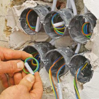
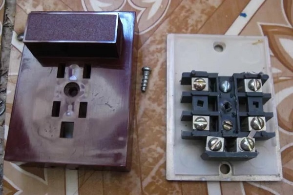
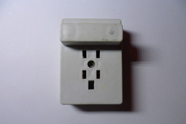
Old and new telephone switching options are presented in the photo selection:
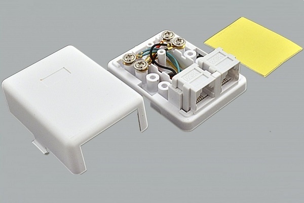
Despite the differences in design and connection methods, any telephone socket traditionally includes three main elements:
- Housing - made of dielectric material (ceramic or plastic).
- Contacts - spring-loaded brass elements, ensuring reliable passage of currents through the electric circuit.
- Terminals - adapters required for connecting wires.
The electrical contact sockets of a stationary outlet are recessed into the housing. This solution protects the device from accidental short circuits.
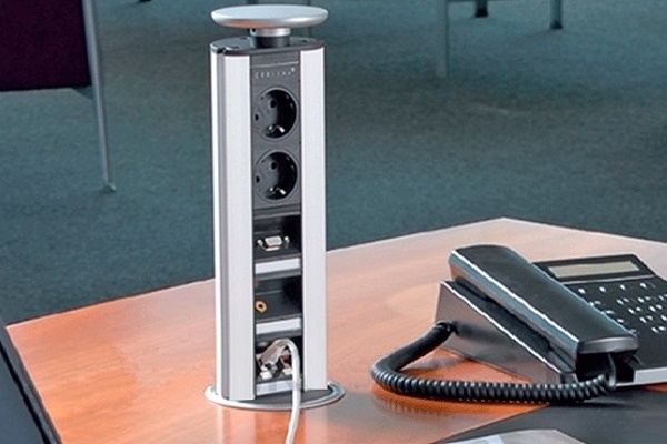
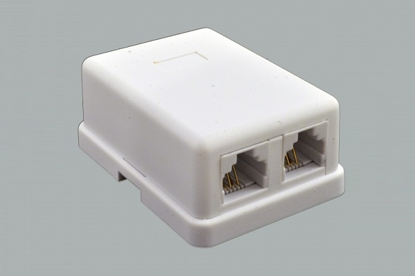
On sale there are single and multi-connector models. The first ones are intended for connecting one device, the second ones allow you to switch several devices at once.

Old and modern device standards
As the equipment improved, the methods for connecting phones to the communication network experienced a number of changes. In the first models of telephone sets, connection to the communication line was carried out completely without the use of sockets.
To create a closed current loop, the wires were simply twisted together, or connected using any other available means.
In the 80s of the last century, PBX lines were connected using two-wire copper wires. And to ensure quick-disconnect connection of the phone, sockets and plugs of the RTShK-4 standard were used. This abbreviation stands for "socket for four-pin type plug-in phones."

The design of the RTShK-4 includes a key and two pairs of contacts. The first pair provides the phone in normal mode, the second - allows you to connect an additional line, provided that both devices are on the same phone number.
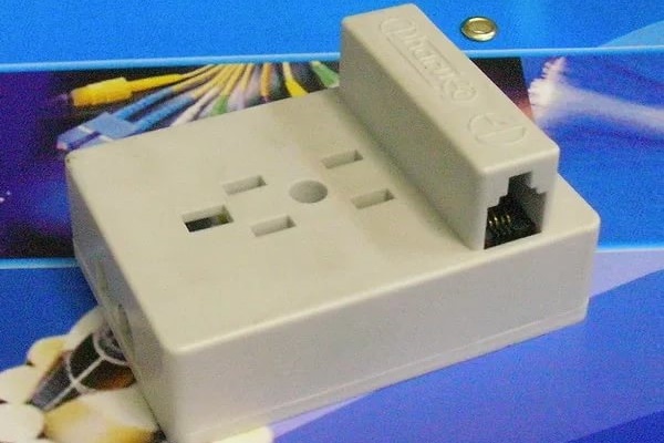
Instead of obsolete models of the RTShK-4 standard, as a result of the widespread dissemination of microprocessor technologies, Registered Jack equipment marked “RJ” was actively used. It complies with the international standards IEC 60884-1 and 60669-1.

Connecting modern stationary phone models for use at the household level is carried out through outlets equipped with one pair of contacts. Cases of such devices are mounted in the cavity of the plastic module and are identified by RJ-11 symbols.
Between the two contacts, which are compact metal plugs, the conductors of the supply wire are buried.RJ-11 standard models are recommended for connecting devices to telephone lines of linear type.

To connect two devices to separate lines and create office PBXs, devices of the RJ-12 and RJ-14 standard are used. Universal four-wire connectors are suitable for most telephone equipment models.
To connect several devices at once, you only need to assemble the sockets in series into blocks, observing the scheme: the first line is connected to contacts No. 2 and No. 3, and the second - to No. 1 and No. 4. Devices of this series are more used to create mini-automatic telephone exchanges for the arrangement of office premises.

Installation of the adapter allows you to connect the plugs of both old and new standards with lines equipped with the use of modern technology.
The main difference between RJ-25 devices is three pairs of working contacts. For this reason, the connection of such equipment can only be performed by a qualified specialist who is well versed in telephony and electrics.

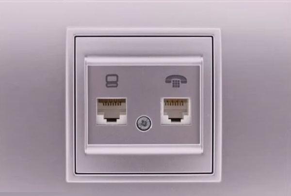
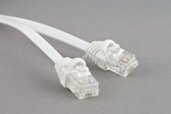
At connecting computer systems, faxes, modems and other complex devices of communication devices also use the RJ-45 standard. When connecting devices RJ-45 standard the focus is on matching plastic keys.
Despite the structural differences between the old and new standards, the device plugs have similar connectors and dimensions. The device is connected to the network through only two contacts. Only modern models use only medium contacts.
Those wishing to get acquainted with the features of the connection will help the photo gallery:
Wiring diagrams and connection methods
Connecting a telephone jack is much simpler than its electrical counterpart. But a process that involves working with low, but still voltage, requires accuracy and caution.

When installing a telephone jack, you can use one of two installation methods:
- open - involves installation in a way;
- closed - in which the telephone line is hidden inside the wall.
When choosing a method of laying, they are guided by the design of the walls, the service conditions of the communication line and the pretentiousness of the design of the room itself. Overhead sockets do not look very aesthetically pleasing, but they are ideal in service speed: they can be removed from the support in a matter of minutes and the integrity of the contacts can be assessed.

To protect open wires from mechanical damage, use decorative plastic cable channels. On sale, they are found in the form of wall structures and floor skirtings. It is convenient to monitor the state of the wire in them through one or two sided snap-on panels.
For closed installation, the most common cable is KSPV. The only core of this cable is made of copper wire, and the outer sheath is made of polyethylene, painted white.
The telephone line is also laid using the distribution cable TRP. It has a dividing base. The core of this single-pair wire is also made of copper and insulated with polyethylene.

To decorate the connection points and make them less noticeable to the eyes of strangers, the devices are placed behind TV screens and monitors, as well as embedded behind the facade of wall furniture.
A separate line is to highlight the sockets built into the baseboard. The main thing is to choose models whose front panel fits snugly to the surface of the baseboard. Otherwise, over time, it will begin to move away from the base, exposing unsightly seams.
How to connect a telephone wall jack
When installing a telephone jack, it should be borne in mind that the voltage for low-current communication devices does not exceed 60 volts. But even a low voltage can still create a current, causing discomfort to a person.
At the moment when a call is made over the telephone line, the voltage rises altogether to an indicator of 110-120 Volts. And it is capable of giving serious pain when contacted. To a value of 12 volts, it decreases only after removing the tube.

The principle of placement and the installation method of telephone outlets practically does not differ from the technology for installing electrical outlets. Since today devices with the J-11 and J-12 standard are the most common, we will consider the subtleties of connecting a telephone socket using their example.
Stage # 1: Conducting the preparatory work
The first thing to do is study the patterns of internal communication. They are attached to the instructions for the product.
When connecting the J-11 and J-12 standards, there should be no problems: you just need to connect the wires of the corresponding polarity. The main thing is that in a suitable plug to the device, the wires are output in a mirror image of the contacts of the outlet.
If you unknowingly purchased and plan to install the J-25 standard, the design of which involves 6 contacts, use only the 3rd and 4th contacts to connect.

When planning to use the device of the old standard, it is worth worrying about purchasing a universal outlet in advance. It is equipped with a four-pin connector and connector. In addition to the outlet itself, it is also necessary to prepare a two-wire wire with a cross section of 0.3-0.5 mm.
It is necessary in advance to identify and map a place and mounting height.
Of the tools for the work necessary to prepare:
- building level;
- cross knife;
- voltmeter;
- a screwdriver;
- nippers;
- lead pencil;
- protective gloves;
- Double-sided tape;
- punch (if mounting a new point).
When choosing a screwdriver, they are guided by the type of surface and the dimensions of the screws used for fastening. To minimize the likelihood of electric shock, all manipulations are best performed with a screwdriver, the handle of which is insulated.

To connect a socket of a hidden type, you must first make a hole in the wall for its installation - undergrowth. This can be done using a hammer drill equipped with a special crown with a diameter of 60-70 mm.
For lack of such work, you can perform the usual hammer with a chisel. But manual labor will take much more time and effort. Then, to the hole made, it is necessary to dig a channel for laying the telephone cable.
There are certain nuances when installing a socket in drywall wall.
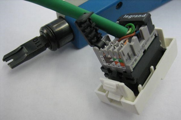
Stage # 2: Stripping ends lived
Before starting to melt the cores, it is necessary to strip the ends of the wires, eliminating the outer layer. Bare enough extreme 4 cm of wire.
When stripping a telephone cable, remember that it is very vulnerable to damage. And broken cores will only lead to equipment malfunctions. Therefore, it is important to use a specialized stripping tool.
Since it is not always possible to accurately perform cutting from the first try, experienced craftsmen recommend making a certain margin along the cable when laying the cable. The excess wire can then be hidden under the cover of the device.

The master’s task is to strip the ends of the wires from the braid so that they are intact and devoid of any defects when exposed.
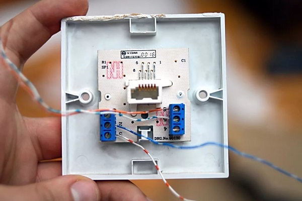
Step # 3: Connecting the Outlet Wires
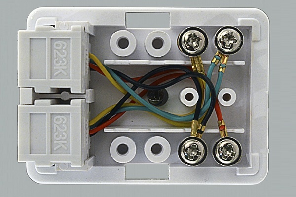
Stripped wires with open cores are connected to the connectors of the box itself, focusing on the designations indicated on the front panel of the indoor unit. With a closed installation method, for the convenience of connecting, wires are made protruding from the wall plane by 50-80 mm.
Experts recommend checking the polarity of contacts when connecting wires, using a tester for this.

If the rule is not respected, taking into account the polarity, there is a great risk that the telephone will malfunction from time to time during operation.
At this stage, a voltmeter is required. With it, you need to check the readiness of the communication line. The voltage in the line should be between 40-60 volts.
The lead-in cable cores are applied to the clamp and tightly tightened with special screws, ensuring a secure fit. The shape of the grooves to which the cores are attached facilitates the installation process. The joints of electrical tape do not need to be wrapped.

Carrying out open installation, at the final stage it remains only to close the housing cover with the latch and fix it with screws. The finished outlet is attached to the wall or floor, "planting" it on a double-sided tape.
With a closed installation method, making sure that the wires are not intertwined in the socket, according to the marking applied, the indoor unit is mounted on the wall. After giving the block the desired position, the structure is fixed with spacer screws and self-tapping screws.
At the final stage, it remains only to eliminate the gaps between the socket and the wall, covering it with gypsum mortar, and also to seal the channels with the laid telephone cable.
After the gypsum has acquired the desired strength, put in place the protective edging and attach the front panel. In modern devices, the protective edging is latched onto the indoor unit, and the front panel is attached by screwing in screws.
If you need to connect a multi-outlet, allowing you to install multiple telephones, you must adhere to the same technology as when installing the classic version of the device. The only difference between the process is the increase in the number of conductors requiring connection.
Conclusions and useful video on the topic
Device Connection Guide:
Replacing an old outlet with a combined RTShK-4 and RG-11 connector with a similar new device:
There is nothing difficult in connecting a telephone wall jack. The only thing - you should not save money by purchasing equipment of a low price range. It does not always comply with the standards and can fail even at the stage of connection.
Share your personal experience with plugging in a telephone jack, leave comments on the article, and ask questions. The contact form is located below.
 How to connect an outlet block: installation rules and connection diagrams
  How to connect an LED switch: rules for connecting a backlit switch
 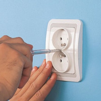 How to connect a double outlet: installing a double outlet in one socket
 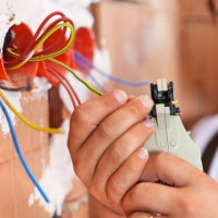 How to install and connect an outlet with grounding: learn to ground the outlet
  How to connect a light bulb through a switch: schemes and connection rules
 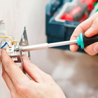 How to install and connect an outlet: a step-by-step guide
  How much does it cost to connect gas to a private house: the price of organizing gas supply
  The best washing machines with dryer: model rating and customer tips
  What is the color temperature of light and the nuances of choosing the temperature of the lamps to suit your needs
  Replacement of a geyser in an apartment: replacement paperwork + basic norms and requirements
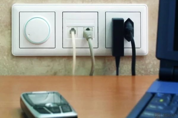
Of course, we must slowly move away from the sockets of the old model and switch to new ones. By the way, it’s generally more promising to even make general wiring for RJ 45. At least, the wiring functionality will increase. I also highly recommend buying a normal cross instrument before installing outlets of a new sample. As a result, not only will it be possible to complete the work faster, but the contacts will be more reliable.
I connected my first telephone jack with a poke method. He was using a screwdriver then, I myself am surprised at how miraculously everything worked for me. And then started a repair, it was necessary to install everything beautifully. Did everything approximately as you wrote. In the first and second cases, I did not pay attention to polarity, and I didn’t have a tester either. So I, an ignoramus, still did not know where the “minus” is, and where the “plus” is.
Still, it’s not clear how to connect 2 phones to one socket, so that when you pick up the handset of one phone, only beeps are heard in the second phone.
Good afternoon, Aristarchus. The article does not solve a similar question. For parallel telephones located in different apartments (the situation of the last century, when communication was the property of privileged people), blockers were used.
The device allowed alternate conversations - subscriber “A” talked, for example, with the calling subscriber “B”, and subscriber “C” was waiting for the end of the conversation to call “D”. Sometimes people scandalized: “I had to urgently call, and you arranged a press conference.”
I will not describe the operation of the blocker - I just attached a screenshot of the circuit with an explanation. There were other device options that expanded the capabilities of the PBX.