How to connect an LED switch: rules for connecting a backlit switch

To perform basic electrical work, it is not necessary to call a master. Knowing how to connect the LED switch, you can independently carry out its installation. You must admit that such a skill is especially useful if a major overhaul and renewal of electrical wiring is to be done.
We will talk about the wiring diagram, the installation method and the difficulties that may arise during installation. You can also do it yourself to improve a conventional switch by making it backlight.
The content of the article:
How the illuminated switch works and works
We describe the design of the LED switch using the example of a two-key device with backlight.
The mechanism consists of the following elements:
- one input, two output terminals;
- current limiting resistor;
- movable contacts.
The design also includes a body, a decorative panel and key pads.

When the contacts of the LED switch are opened, the current flowing through the phase wire is supplied to the resistor, then to the LED or neon lamp. Further, the voltage passes through the light and exits through zero.
Since the backlight is connected through a current-limiting resistor, the voltage in the network decreases and it is enough for backlighting, but not enough for the chandelier to work.

After closing the contacts of the switch, the current, which always moves along the circuit with the least resistance, passes through the network supplying the lighting lamp - in this circuit the voltage is almost zero. Current is also supplied to the backlight circuit, but it is so small that it is not enough even for a neon lamp to work.

LED switch application
A switch equipped with a backlight is installed where it is dark even in the daytime, and the constant use of a lighting device is impractical. It is also used in rooms, access to which is necessary at night.

The more light sources, the more keys will be required on the switch. To control lighting, consisting of more than three lighting devices, type-setting switches are used, which are installed in one row.
To control lighting from several places, they acquire a special passage switch with backlight.
How to choose an LED switch
When buying an LED switch, there is no need to chase expensive ceramic devices, since the power consumption of lighting devices is generally not very large.
In conditions of domestic use, it will be enough to use a high-quality plastic LED switch with a reliable contact group. The resource of such devices is about 40,000 switching.

They also make a choice based on the design of the device, the type of inclusion - they produce keyboard and rotary, button, touch and cord.
The installation method distinguishes between internal and external devices. The case material may also be different - they use plastic, glass, copper, stainless steel, and shale, gilding and even leather are used as a decorative coating.
But what you really need to pay attention to is security class (IP) - it indicates the possibility of using the equipment in certain conditions.
For instance:
- IP class from 20 indicates that the device is poorly protected from dust and moisture. Such equipment is used in residential premises.
- IP class 45 and above It is used to mark switches suitable for connection in rooms with high humidity - bathtubs, baths, kitchens, toilets, etc.
- Class with IP from 65 means that the switch can be used outdoors. Such electrical equipment has increased protection against dust, moisture. It is installed outside the building - under the porch, canopy, on covered verandas. It has more massive keys, and in the place of entry of the electric wire rubber seal.
The higher the class, the more protected the device is from external factors. This applies not only to switches, but also to sockets, toggle switches, and other electrical equipment.
How to install
The backlit switch mechanism suggests a small lamp that glows when it is turned off. A small neon lamp or LED along with a resistance element can be used to illuminate the device. The wires stretch from the backlight, which must be connected to power during installation.
Preparing for installation and mandatory security measures
Without basic safety knowledge, it’s better not to start working with electrical equipment at all. Illiterate electrical installation can lead to electric shock, failure of electrical appliances, fire.
Basic rules of conduct when working with electricity:
- all work must be carried out in a de-energized network;
- it is unacceptable to overload the power grid;
- check wire marking compliance with the connected network;
- it is better to replace the damaged network section rather than repair it;
- Do not touch the connected equipment with wet hands.
To determine the nature of the conductors - where is zero and where is the phase - will help a conventional screwdriver indicator or multimeter. The indicator is sufficient if the electrical network is single-phase. To analyze a three-phase network, a multimeter is used.

Installation example of a 2-key switch with backlight
The main structural differences of LED switches are in the backlight mechanism. It can be ready to use and does not require any action to connect it. In another type of design, it is necessary to connect wires that feed the LED or neon lamp.
Consider a more complex option - how to connect a backlit device in which the conductors need to be connected independently.

First of all, they fake the keys with a screwdriver or other suitable tool and remove them. Separate the core (internal mechanism) from the body.
Next, determine the correct position of the switch using the indicator. To do this, by touching the contacts with a screwdriver on one side and an indicator on the other, they check whether the device is turned on or off.
If the indicator lights up, it means it is on. In this state, turn it so that the keys with the pressed side are located on top.

One of the wires coming from the indicator is connected to the input terminal, and the second is connected to the key contact. If there are several keys, then the wire is connected to the first of them, starting from the left. Simultaneously with the wire going from the indicator to the input terminal, a phase conductor is also connected.
Two branch phase wires that go to the chandelier are connected to the output terminals simultaneously with the second backlight wire, making sure that it does not fall out of contact.
With this connection method, the backlight will turn on after opening the contacts using the first key. The second will have no effect on turning off the backlight, and the lamp will light even when the light is on.
In order for the indicator light to go out when you press any of the keys, you must independently make a jumper that will connect the indicator to both keys.
If you do not take into account the connection of the backlight, the installation takes place as in a conventional device. Across junction box a phase conductor is led to the switch and connected to the input terminal L, leading it into the hole and screwing it.
Next, to the contacts of the device L1 and L2 are connected two outlet phase wires that lead to the chandelier also through a junction box. One of them is connected to one lamp, the other to the other two. Zero passes through the soldering unit in the mounting box, then goes to all the lamps of the chandelier, closing the contact.

Why are energy-saving lamps blinking?
LED switch incompatible with operation energy saving lamps. The conflict of devices is manifested in a short flash of the lamp in the off state or in the so-called smoldering mode, when the lamp does not turn off completely and barely glows.

This happens because inside the fluorescent lamp there is an electronic converter (capacitor), which gradually recharges from the current passing through the backlight, flashes.
A similar phenomenon occurs with power supplies of LED strips, which also have a capacitor, and which is powered by a small current coming from a backlit switch.
Manufacturers of energy-saving lamps indicate that the use of their products is not compatible with the use of LED switches and dimmers.
You can get around this limitation if you control the operation of the lighting device using a relay. From the switch, the command first comes to the relay, which already directly controls the lighting.
The relay is produced by many manufacturers of electrical products: Schneider electric, ABB, Siemens. It can be placed under the cap of the chandelier, behind the ledge in which the LED ruler is installed.
You can apply another solution to the problem - disconnect the neon lamp or LED from the power supply. This can be done by disconnecting the backlight wires from the terminals. But then the LED switch will lose its advantages.
Consider solutions that still allow you to combine backlighting and the use of energy-saving lamps.
How to combine lamps and switch
If after switching off the fluorescent lamp blinks or glows weakly, the problem can be fixed by connecting an additional resistance (resistor or capacitor) in parallel with the lighting point.
To do this, you need a resistor with a nominal value of 50 kΩ and a power of 2 watts. It will absorb excess current when the backlight is on and will not allow the lamp capacitor to charge.

This method of eliminating the cause of the blinking of energy-saving lamps is considered quite dangerous and experienced electricians do not recommend using it without sufficient skills in conducting electrical work.
It is better to use a ready-made protection unit for fluorescent and LED lamps, which eliminates flickering, protects against power surges, and eliminates interference from the lamps. Its connection is mandatory if a backlit switch is used.

The protective unit is connected in parallel with lamps that do not work correctly - they flicker or glow weakly when turned off. Install it in the lamp housing or in the chandelier glass.

Solutions to the popular problems and malfunctions of LED lamps are detailed in these articles:
- Why LED lamps light when the switch is off: reasons and solutions
- Why the LED bulbs blink: troubleshooting + how to fix
- DIY LED lamp repair: the causes of breakdowns, when and how you can repair it yourself
DIY light switch
During the operation of electrical equipment, it sometimes turns out that in some of the rooms it would be nice to have a switch backlight. To do this, it is not necessary to buy a device - you can independently improve the old one.
What is needed for this:
- ordinary switch;
- LED with any characteristics;
- 470 kΩ resistor
- diode 0.25 W;
- the wire;
- soldering iron;
- drill.
Using a soldering iron, they begin to assemble the circuit. The cathode of the diode (marked with a black bar) is connected to the anode of the LED (the leg is longer at the anode). The resistor is soldered to the positive contact of the LED and to the wire, which will serve as a connection to the switch. The second wire is connected to the cathode of the LED.

Next, connect everything to the on-off mechanism. The phase conductor that leads to the lamp is connected to the terminal along with one of the wires leading to the LED. Another wiring is connected to the input terminal along with a phase wire that supplies current from the mains.
It is necessary to carefully insulate the exposed sections of the wire and exclude the contact of the conductors to the body, this is especially important if it is metal.
Check the connection diagram of the backlit switch for operability as follows: the button, closing the contact, causes the chandelier or lamp to light up, in the off state the LED lamp lights up. If the circuit works correctly, you can install the device in the housing.
So that lighting can be seen, the LED lamp is brought into the drilled hole at the top of the housing. It is not necessary to do this if the case is light - light will break through it.

On / Off switch
Switches with indicators differ from LEDs by a completely different principle of use - the lamp in them lights up when the lighting is on. The main purpose of the control lamp is to signal that the lighting is on in the basement, in the attic, in the pantry or on the street.
Used to control power consumption. The indicator can be set for each of the keys or only for one of them.
The connection and operation of the switch with the backlight function is built according to the following principle. The control lamp is connected in parallel to the terminals of the switch. When the circuit closes, current flows through the indicator and the light - both light up. If the switch is turned off, no current flows either to the indicator or to the lamp.

Conclusions and useful video on the topic
Instructions for connecting the LED switch:
How to set your own backlight:
What to do if energy-saving lamps glow or blink after turning off:
A backlit switch can participate in almost all electrical lighting circuits. But for its proper installation, it is necessary to study the design, the principle of operation and the nuances that arise when interacting with other electrical equipment.
Share with your readers your experience with connecting an LED switch. Please leave comments, ask questions about the topic of the article and participate in discussions - the feedback form is located below.
 How to connect a light bulb through a switch: schemes and connection rules
 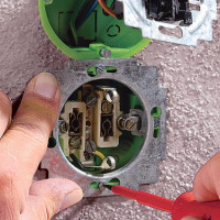 How to connect a switch with one key: rules and connection diagrams
  How to choose and correctly connect a three-key switch
  How to connect a double switch to two bulbs: schemes + connection tips
  How to connect a telephone socket: connection diagram and installation rules
 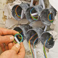 How to connect an outlet block: installation rules and connection diagrams
  How much does it cost to connect gas to a private house: the price of organizing gas supply
  The best washing machines with dryer: model rating and customer tips
  What is the color temperature of light and the nuances of choosing the temperature of the lamps to suit your needs
  Replacement of a geyser in an apartment: replacement paperwork + basic norms and requirements
I'm not particularly friendly with the electrician. Somehow I put an energy-saving lamp in a switch with a dimer and did not immediately notice that it began to flash, and then left it that way. The lamp was in the corridor, blinking brightly enough, I did not need to turn on the light to go out at night, everything was visible. In theory, it should have burned quickly, but it still works. So, the service life has not changed, it may have hit a quality one.