Solid State Relays: Types, Practical Applications, Wiring Diagrams

Classic starters and contactors are gradually becoming a thing of the past. Their place in automotive electronics, household appliances and industrial automation is occupied by a solid-state relay - a semiconductor device in which there are no any moving parts.
The devices have various designs and wiring diagrams, on which their fields of application depend. Before using the device, you need to understand its operating principle, learn about the features of the operation and connection of different types of relays. Answers to these questions are detailed in the article.
The content of the article:
Solid State Relay Device
Modern solid-state relays (TTRs) are modular semiconductor devices that are power electrical switches.
The key working nodes of these devices are represented by triacs, thyristors or transistors. TTRs do not have moving parts, which differs from electromechanical relays.

The internal structure of these devices can vary greatly depending on the type of adjustable load and the electrical circuit.
The simplest solid-state relays include the following nodes:
- input node with fuses;
- trigger chain;
- optical (galvanic) isolation;
- switching node;
- protective circuits;
- node output to the load.
The input node TTR is a primary circuit with a series-connected resistor. A fuse in this circuit is optional. The task of the input node is to accept a control signal and transmit a command to the load switching switches.
With alternating current, galvanic isolation is used to separate the control and the main circuit. The principle of the relay operation largely depends on its device.The trigger circuit responsible for processing the input signal may be included in the optical isolation unit or located separately.
The protective unit prevents overloads and errors, because in the event of a device breakdown, the connected equipment can also fail.
The main purpose of solid-state relays is to close / open the electrical network using a weak control signal. Unlike electromechanical analogues, they have a more compact shape and do not produce characteristic clicks during operation.
The principle of operation of the TTR
The operation of a solid state relay is quite simple. Most TTRs are designed to control automation in networks of 20-480 V.

In the classic version, two contacts of a switched circuit and two control wires are included in the device case. Their number can change with an increase in the number of connected phases. Depending on the presence of voltage in the control circuit, the main load is turned on or off by the semiconductor elements.
A feature of solid state relays is the presence of infinite resistance. If the contacts in electromechanical devices are completely disconnected, then in solid-state the absence of current in the circuit is ensured by the properties of semiconductor materials.
Therefore, at high voltages, small leakage currents may occur that can adversely affect the operation of the connected equipment.
Solid State Relay Classification
The scope of the relay is diverse, therefore, their design features can vary greatly, depending on the needs of a particular automatic circuit. TTRs are classified by the number of connected phases, type of operating current, design features and type of control circuit.
By the number of connected phases
Solid state relays are used both as part of home appliances and in industrial automation with an operating voltage of 380 V.
Therefore, these semiconductor devices, depending on the number of phases, are divided into:
- single phase;
- three phase.
Single Phase TTR allow working with currents of 10-100 or 100-500 A. Their control is carried out using an analog signal.

Three Phase Solid State Relays capable of passing current in the range of 10-120 A. Their device involves a reversible principle of operation, which ensures the reliability of the regulation of several electrical circuits simultaneously.
Often three-phase SSRs are used to provide an induction motor. In his control circuit, fast fuses are necessarily included due to high inrush currents.
By type of operating current
Solid state relays cannot be configured or reprogrammed, so they can only work properly with a certain range of mains electrical parameters.
Depending on the needs, TTR can be controlled by electric circuits with two types of current:
- permanent;
- variables.
Similarly, it is possible to classify TTR by the type of active load voltage. Most relays in household appliances operate with variable parameters.

Devices with a constant control current are characterized by high reliability and use a voltage of 3-32 V for regulation. They withstand a wide temperature range (-30 .. + 70 ° C) without significant changes in characteristics.
Relays controlled by alternating current have a control voltage of 3-32 V or 70-280 V.They are distinguished by low electromagnetic interference and high response speed.
By design features
Solid state relays are often installed in the common electrical panel of an apartment, so many models have a mounting block for mounting on a DIN rail.
In addition, there are special radiators located between the TTR and the supporting surface. They allow you to cool the device at high loads, while maintaining its performance.

Between the relay and the radiator, it is recommended to apply a layer of thermal paste, which increases the contact area and increases the heat transfer. There are also TTRs designed for fastening to the wall with ordinary screws.
By type of control scheme
Not always the principle of operation of an adjustable relay technology requires its instantaneous operation.
Therefore, manufacturers have developed several TTR control schemes that are used in various fields:
- Control "through zero". This option of controlling a solid-state relay assumes operation only when the voltage value is 0. It is used in devices with capacitive, resistive (heaters) and weak inductive (transformers) loads.
- Instant. It is used when sharp relay operation is necessary when a control signal is applied.
- Phase. It assumes the regulation of the output voltage by changing the parameters of the control current. It is used to smoothly change the degree of heating or lighting.
Solid state relays differ in many other, less significant, parameters. Therefore, when buying a TTR, it is important to understand the operation scheme of the connected equipment in order to purchase the most appropriate adjustment device.
A power reserve must be provided, because the relay has an operational resource that is quickly consumed with frequent overloads.
Advantages and disadvantages of TTR
Solid-state relays are not in vain crowding out conventional starters and contactors from the market. These semiconductor devices have many advantages over electromechanical counterparts, which make consumers opt for them.

These advantages include:
- Low power consumption (90% less).
- Compact dimensions for mounting devices in a limited space.
- High start and shutdown speed
- Reduced operation noise; there are no clicks characteristic of an electromechanical relay.
- No maintenance is expected.
- Long service life thanks to a resource of hundreds of millions of operations.
- Due to the wide possibilities for modifying electronic components, TTRs have extended fields of application.
- Lack of electromagnetic interferences at operation.
- Corruption of contacts due to their mechanical shock is excluded.
- Lack of direct physical contact between control and switching circuits.
- Ability to regulate the load.
- The presence in the pulsed TTR of automatic circuits that protect against overloads.
- Possibility of use in explosive atmospheres.
The indicated advantages of solid-state relays are not always sufficient for normal operation of the equipment. That is why they have not yet completely replaced electromechanical contactors.

TTR also have disadvantages that do not allow them to be used in many cases.
The minuses include:
- The inability of most devices with voltages above 0.5 kV.
- High price.
- Sensitivity to high currents, especially in the starting circuits of electric motors.
- Restrictions on use in high humidity conditions.
- A critical decrease in performance at temperatures below 30 ° C frost and above 70 ° C heat.
- The compact case leads to excessive heating of the device at stably high loads, which requires the use of special passive or active cooling devices.
- The ability to melt the device from heating during a short circuit.
- Microcurrents in the closed state of the relay can be critical for the operation of the equipment. For example, fluorescent lamps connected to the network may flash periodically.
Thus, solid state relays have specific applications. In the chains of high-voltage industrial equipment, their use is sharply limited due to the imperfect physical properties of semiconductor materials.
However, in household appliances and the automotive industry, TTRs occupy a strong position due to their positive properties.
Possible wiring diagrams
Solid-state relay connection schemes can be very diverse. Each electrical circuit is built based on the characteristics of the connected load. Additional fuses, controllers, and control devices may be added to the circuit.

Next, the most simple and common TTR connection schemes will be presented:
- normally open;
- with connected circuit;
- normally closed;
- three-phase;
- reversible.
Normally open (open) circuit - a relay, the load of which is energized in the presence of a control signal. That is, the connected equipment is turned off when the inputs 3 and 4 are de-energized.

Normally Closed Circuit - a relay is meant, the load in which is energized in the absence of a control signal. That is, the connected equipment is in working condition with de-energized inputs 3 and 4.
There is a solid-state relay connection scheme in which the control and load voltage are the same. This method can be used simultaneously for work in DC and AC networks.
Three phase relays connected by a slightly different principles. Contacts can be connected in the options "Star", "Triangle" or "Star with neutral."

Solid State Reverse Relays are applied in electric motors in the corresponding mode. They are manufactured in a three-phase version and include two control loops.

It is only necessary to assemble electrical circuits with TTRs after they have been pre-drawn on paper, because improperly connected devices can fail due to a short circuit.
Practical use of devices
The scope of use of solid-state relays is quite extensive. Due to their high reliability and lack of need for regular maintenance, they are often installed in hard-to-reach areas of equipment.

The main areas of application of TTR are:
- Thermoregulation system with the use of heating elements;
- maintaining a stable temperature in technological processes;
- transformer operation control;
- lighting adjustment;
- motion sensor circuits, lighting, photosensors for street lighting etc.;
- electric motor control;
- uninterruptible power supplies.
With the increase in automation of household appliances, solid-state relays are becoming more widespread, and developing semiconductor technologies are constantly opening up new areas of their application.
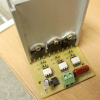
If desired, you can assemble a solid-state relay yourself. Detailed instructions are provided in this article.
Conclusions and useful video on the topic
The presented videos will help to better understand the operation of solid-state relays and get acquainted with the methods of their connection.
A practical demonstration of the operation of a simple solid-state relay:
Analysis of varieties and features of the operation of solid-state relays:
Testing the operation and degree of heating of the TTR:
Almost everyone can mount an electric circuit from a solid-state relay and a sensor.
However, planning a work circuit requires basic knowledge in electrical engineering, because improper connection can lead to electric shock or short circuit. But as a result of the correct actions, you can get a lot of useful devices in everyday life.
Is there anything to supplement, or have questions about connecting and using solid state relays? You can leave comments on the publication, participate in discussions and share your own experience using such devices. The contact form is located in the lower block.
 DIY Solid State Relay: Assembly Instructions and Connection Tips
  Electromagnetic relay: device, marking, types + subtleties of connection and adjustment
  Thermal relay: operating principle, types, connection diagram + adjustment and marking
  Intermediate relay: how it works, labeling and types, nuances of adjustment and connection
  Time relay: operating principle, wiring diagram and tuning recommendations
 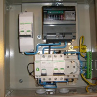 Connection diagrams of magnetic starter for 220 V and 380 V + features for independent connection
  How much does it cost to connect gas to a private house: the price of organizing gas supply
  The best washing machines with dryer: model rating and customer tips
  What is the color temperature of light and the nuances of choosing the temperature of the lamps to suit your needs
  Replacement of a geyser in an apartment: replacement paperwork + basic norms and requirements
And if I have constant voltage drops in the apartment, what should I do? Approximately 180-250 V, what to do and where to go?
In fact, this is a fairly common problem for many areas in the cities of the entire post-Soviet space. Since you have an apartment, the problem is relevant not only for you, perhaps for the entire entrance, at home or even in the area. Therefore, it is best to file a collective application to eliminate the problem of voltage drops.
Representatives of the company with which you have a contract for the supply of electricity should deal with this problem. Also for the future, I advise you to use stabilizers and voltage relays, namely in a bundle, and not separately. The former are effective at low voltage, and the latter at high.