DIY Solid State Relay: Assembly Instructions and Connection Tips

Solid State Relay (TTR) is a device from a series of electronic components of non-mechanical action. The lack of mechanics opens up more opportunities for electronics lovers to make a solid-state relay with their own hands for personal use.
Consider this possibility in more detail.
The content of the article:
Design and principle of operation of the TTR
If most of such electronics traditionally contains moving parts of contact groups, a solid-state relay does not have such parts at all. Switching the circuit with a device circuit is carried out according to the principle of an electronic key. And the role of electronic keys is usually played by semiconductors built into the body of the relay - power transistors, triacs, thyristors.
Before you try to make a solid-state relay yourself, it is logical to familiarize yourself with the basic design of such devices, to understand the principle of their operation.

In the framework of a tight study of the device, it is immediately necessary to highlight the advantages of the TTR:
- high load switching;
- high switching speed;
- perfect galvanic isolation;
- ability to briefly hold high overloads.
Among mechanical structures, it is not really possible to find relays with similar parameters. In general, the advantages over the mechanical counterparts of solid state relays are expressed by an impressive list.

Operating conditions for TTR practically do not limit the use of these devices. In addition, the absence of moving mechanical parts favorably affects the service life of the devices.So there is every reason to tackle a solid-state relay - to assemble the device with your own hands.
However, in fairness, along with the positive aspects, it should be noted the properties of the relay, characterized as flaws. So, for the operation of powerful devices, as a rule, an additional component of the structure is required, which is designed to remove heat.

Solid-state relay cooling radiators have overall dimensions several times greater than the dimensions of the TTR, which reduces the convenience and rationality of installation.
TTR devices during operation (in the closed state) give a reverse leakage current and show a non-linear current-voltage characteristic. Not all solid state relays can be used without restrictions in the characteristics of the switched voltages.

Certain types of devices are designed to switch only direct current. The introduction of solid-state relays in the circuit usually requires additional measures aimed at blocking false alarms.
Solid state relays can often be found in common electrical panel of the apartment.
How does a solid state relay work?
The control signal (usually a low voltage, emanating, for example, from the control controller) is supplied to the LED of the optoelectronic pair present in the TTR circuit. The LED begins to emit light towards the photodiode, which in turn opens and begins to pass current.

The current passing through the photodiode comes to the control electrode of the key transistor or thyristor. The key opens, closes the load circuit.
This is how the device switching function works. All electronics are traditionally enclosed in a monolithic enclosure. Actually, therefore, the device was called a solid-state relay.
And how to connect a solid-state relay can be found in this stuff.
Solid State Switches
The entire existing range of devices can be conditionally divided into groups based on the category of the connected load, the features of voltage control and switching.
Thus, a total of three groups will be drawn:
- Devices operating in DC circuits.
- Devices operating in AC circuits.
- Universal designs.
The first group is represented by devices with parameters of working control voltages of 3 - 32 volts. This is a relatively small-sized electronics, endowed with LED indicators, capable of functioning without interruption at temperatures of -35 / +75 ºС.

The second group - devices designed for installation in AC networks. Here are the designs of TTR for installation in AC networks, controlled by a voltage of 24 - 250 volts. There are devices capable of switching high power loads.
The third group is universal devices. The circuitry of this type of device supports manual tuning for use in certain conditions.
If we take into account the nature of the connected load, we should distinguish two types of solid-state AC relays: single-phase and three-phase. Both types are designed for switching a sufficiently powerful load at currents of 10 - 75 A.In this case, peak short-term current values can reach 500 A.

Capacitive, resistive, induction circuits can act as a load switched by solid-state relays. The design of the switches allows you to smoothly control, for example, heating elements, incandescent lamps, electric motors without unnecessary noise.
Reliability is sufficiently high. But in many ways, the stability and durability of solid-state relays depends on the quality of production. Thus, devices manufactured under a certain Impuls trademark are often marked with a short service life.
On the other hand, Schneider Electric products leave no room for criticism.
How to make TTR with your own hands?
Given the design feature of the device (monolith), the circuit is not assembled on a textolite board, as is customary, but on a wall-mounted installation.

There are many circuit solutions in this direction. The specific option depends on the required switching power and other parameters.
Electronic components for circuit assembly
The list of elements of a simple circuit for the practical development and construction of a solid-state relay with your own hands is as follows:
- Optocoupler type MOS3083.
- Triac type VT139-800.
- KT209 series transistor.
- Resistors, Zener diode, LED.
All of these electronic components are soldered by surface mounting according to the following diagram:

Due to the use of the MOS3083 optocoupler in the control signal generation circuit, the input voltage can vary from 5 to 24 volts.
And due to the chain, consisting of a zener diode and a limiting resistor, the current passing through the control LED is reduced to the minimum possible. This solution provides a long service life of the control LED.
Checking the assembled circuit for operability
The assembled circuit must be checked for operability. It is not necessary to connect a load voltage of 220 volts to the switching circuit through a triac. It is enough to connect a measuring device - a tester parallel to the switching line of the triac.

The measurement mode of the tester must be set to "mOhm" and apply power (5-24V) to the control voltage generation circuit. If everything works correctly, the tester should show the difference in resistance from "mOhm" to "kOhm."
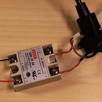
Monolithic housing
An aluminum plate 3-5 mm thick will be required under the base of the future solid state relay case. The dimensions of the plate are not critical, but must comply with the conditions for efficient heat removal from the triac when this electronic element is heated.

The surface of the aluminum plate should be flat. Additionally, it is necessary to process both sides - to peel with a fine sandpaper, polish.
At the next stage, the prepared plate is equipped with a “formwork” - a border made of cardboard or plastic is glued around the perimeter. It should be a kind of box, which will subsequently be filled with epoxy.
An electronic circuit of a solid-state relay assembled by a "canopy" is placed inside the created box. Only a triac is laid on the surface of the aluminum plate.

No other circuit parts or conductors should touch the aluminum substrate. The triac is applied to aluminum by that part of the body, which is designed for installation on a radiator.
You should use a heat-conducting paste on the contact area of the triac body and the aluminum substrate. Some brands of triacs with an uninsulated anode must be placed through a mica pad.

The triac must be pressed firmly to the base with some kind of weight and filled with epoxy glue around the perimeter or secured in some way without disturbing the surface of the back of the substrate (for example, rivets).
Preparation of compound and filling of the body
For the manufacture of a solid body of an electronic device, a compound mixture will be required. The composition of the compound mixture is based on two components:
- Epoxy resin without hardener.
- Alabaster powder.
Thanks to the addition of alabaster, the master solves two problems at once - he receives an exhaustive volume of the filler compound at a nominal consumption of epoxy resin and creates a fill of optimal consistency.
The mixture must be thoroughly mixed, after which you can add the hardener and mix thoroughly again. Next, carefully mount the “wall-mounted” installation inside the cardboard box with the created compound.

Fill is done to the upper level, leaving only a part of the head of the control LED on the surface. Initially, the surface of the compound may not look completely smooth, but after a while the picture will change. It remains only to wait for the cast to solidify completely.
In fact, you can use any suitable casting solutions. The main criterion is that the casting composition should not be electrically conductive, plus a good degree of casting rigidity should be formed after solidification. The molded case of the solid-state relay is a kind of protection of the electronic circuit from accidental physical damage.
Conclusions and useful video on the topic
This video shows how and on the basis of which electronic components a solid-state relay can be made. The author lucidly talks about all the details of the manufacturing practice that he personally encountered during the production of the electronic switch:
Video about the problem that you may encounter after acquiring a single-phase TTR from sellers from China. Along the way, conducts a kind of review of the device switching device:
Self-manufacturing of solid-state relays is a possible solution, but with respect to products under low-voltage load, consuming relatively low power.
It is difficult to make more powerful and high-voltage devices with your own hands. And this financial undertaking will cost the same amount as the factory copy is estimated. So if necessary, it’s easier to buy a ready-made industrial device.
If you have any questions about assembling a solid state relay, please ask them in the comments box, and we will try to give you an extremely clear answer. There you can share the experience of self-production of relays or provide valuable information on the topic of the article.
 Solid State Relays: Types, Practical Applications, Wiring Diagrams
 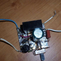 Do-it-yourself time relay: an overview of 3 homemade options
 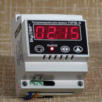 Time relay: operating principle, wiring diagram and tuning recommendations
 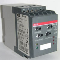 Phase control relays: operating principle, types, marking + how to adjust and connect
  Electromagnetic relay: device, marking, types + subtleties of connection and adjustment
  Thermal relay for an electric motor: operating principle, device, how to choose
  How much does it cost to connect gas to a private house: the price of organizing gas supply
  The best washing machines with dryer: model rating and customer tips
  What is the color temperature of light and the nuances of choosing the temperature of the lamps to suit your needs
  Replacement of a geyser in an apartment: replacement paperwork + basic norms and requirements