Thermal relay: operating principle, types, connection diagram + adjustment and marking

The durability and operational reliability of any installation with an electric motor depends on various factors. However, current overloads significantly affect the life of the motor. To prevent them, they connect a thermal relay that protects the main working body of the electric machine.
We will tell you how to choose a device that predicts the emergence of emergency situations in excess of the maximum permissible current indicators. In the article we presented, the principle of action is described, the varieties and their characteristics are given. Tips on connecting and competent configuration are given.
The content of the article:
Why are protective devices necessary?
Even if the drive is correctly designed and used without violating the basic rules of operation, there is always the possibility of a malfunction.
Emergency modes of operation include single-phase and multiphase faults, thermal overloads of electrical equipment, jamming of the rotor and destruction of the bearing assembly, phase failure.
Operating in high load mode, the electric motor consumes a huge amount of electricity. And with a regular excess of the rated voltage, the equipment heats up intensively.
As a result, insulation quickly wears out, which leads to a significant reduction in the operational life of electromechanical plants. To exclude such situations, a thermal protection relay is connected in the electric current circuit. Their main function is to ensure the normal operation of consumers.
They turn off the motor with a certain delay, and in some cases - instantly, to prevent the destruction of insulation or damage to individual parts of the electrical installation.

In order to prevent a decrease in insulation resistance, protective shutdown devices are used, but if the task is to prevent a violation of cooling, special devices of built-in thermal protection are connected.
The device and the principle of operation of TR
Structurally, the standard electrothermal relay is a small apparatus that consists of a sensitive bimetallic plate, a heating coil, a lever-spring system and electrical contacts.
A bimetallic plate is made of two dissimilar metals, as a rule, Invar and chromium-nickel steel, firmly connected together during the welding process. One metal has a higher temperature coefficient of expansion than the other, so they heat up at different speeds.
In case of current overload, the non-fixed part of the plate bends to the material with a lower coefficient of thermal expansion. This exerts a force effect on the contact system in the protective device and activates the shutdown of the electrical installation during overheating.
Most mechanical thermal relay models have two groups of contacts. One pair is normally open, the other is constantly closed. When the protective device trips, the state of the contacts changes. The former are closed, and the latter become open.

An integrated transformer detects the current, after which the electronics processes the received data. If the current value is currently greater than the setpoint, the pulse is instantly transmitted directly to the switch.
By opening the external contactor, a relay with an electronic mechanism blocks the load. Itself thermal relay for electric motor mounted on the contactor.
The bimetallic plate can be heated directly - due to the influence of the peak load current on the metal strip or indirectly, using a separate thermocouple. Often these principles are combined in a single thermal protection apparatus. With combined heating, the device has the best performance.

Basic characteristics of a current relay
The main characteristic of the thermal protection switch is a pronounced dependence of the response time on the current flowing through it - the larger the value, the faster it will work. This indicates a certain inertia of the relay element.
Directional movement of carrier particles through any electrical device, circulation pump and an electric boiler generates heat. At rated current, its allowable duration tends to infinity.
And at values exceeding the nominal values, the temperature in the equipment rises, which leads to premature insulation wear.

The rated load of the motor itself is a key factor in determining the choice of device. An indicator in the range of 1.2-1.3 indicates a successful operation with a current overload of 30% over a time period of 1200 seconds.
The duration of the overload can adversely affect the state of electrical equipment - with a short-term exposure of 5-10 minutes, only the motor winding, which has a small mass, is heated. And with prolonged, the entire engine heats up, which is fraught with serious damage.Or it may be necessary to replace the burnt equipment with new one.
In order to maximally protect the object from overload, it is necessary to use a thermal protection relay specifically under it, the response time of which will correspond to the maximum permissible overload indicators of a particular electric motor.
In practice, collect voltage monitoring relay under each type of motor is impractical. One relay element is used to protect engines of various designs. At the same time, it is impossible to guarantee reliable protection in the full working interval limited by the minimum and maximum load.

Therefore, it is not absolutely necessary that the protective device react to every, even a slight increase in current. The relay must turn off the motor only in cases where there is a risk of rapid wear of the insulating layer.
Types of thermal protection relays
There are several types of relays for protecting electric motors from phase failure and current overloads. All of them differ in design features, the type of MP used and application in different motors.
TRP. Single pole switching device with combined heating system. Designed to protect asynchronous three-phase electric motors from current overloads. TRP is used in DC power networks with a base voltage of 440 V in normal operation. It is distinguished by its resistance to vibrations and shocks.
RTL. Provide engines with protection in such cases:
- when one of the three phases falls out;
- asymmetries of currents and overloads;
- delayed start;
- jamming of the actuator.
They can be installed with the KRL terminals separately from magnetic starters or mounted directly on the PML. Mounted on standard-type rails, protection class - IP20.
PTT. They protect asynchronous three-phase machines with a squirrel-cage rotor from the delayed start of the mechanism, prolonged overloads and asymmetries, that is, phase imbalance.

TRN. Two-phase switches that control the start-up of the electrical installation and the operation mode of the motor. They are practically independent of the ambient temperature, they have only a system for manually returning contacts to their initial state. They can be used in DC networks.
RTI. Electric switching devices with a constant, albeit low power consumption. Mounted on contactors of the KMI series. Work together with fuses /circuit breakers.
Solid state current relays. They are small electronic devices in three phases, in the design of which there are no moving parts.
They operate according to the principle of calculating average values of motor temperatures, for which purpose constant monitoring of operating and starting currents is performed. They are distinguished by immunity to changes in the environment, and therefore are used in hazardous areas.
RTK. Starting switches for temperature control in the housing of electrical equipment. They are used in automation circuits, where thermal relays act as components.

It is important to remember that none of the above devices is suitable for protecting circuits from short circuits.
Thermal protection devices only prevent emergency conditions that occur during abnormal operation of the mechanism or overload.
Electrical equipment may burn out before the relay starts to operate. For comprehensive protection, they must be supplemented with fuses or compact circuit breakers of a modular design.
Connection, adjustment and marking
The overload switching device, unlike an electric machine, does not break the power circuit directly, but only gives a signal to temporarily shut off the object in emergency mode. A normally switched on contact works like a stop button on a contactor and is connected in series.
Device Connection Diagram
In the design of the relay, it is not necessary to repeat absolutely all the functions of the power contacts upon successful operation, since it is connected directly to the MP. This design allows you to significantly save materials for power contacts. It is much easier to connect a small current in the control circuit than to immediately disconnect three phases with a large one.
In many schemes of connecting a thermal relay to an object, a permanently closed contact is used. It is connected in series with the stop key of the control panel and is designated NC - normally closed, or NC - normal connected.
An open contact with such a circuit can be used to initiate the operation of thermal protection. The connection diagrams of electric motors in which the thermal protection relay is connected can vary significantly depending on the availability of additional devices or technical features.

This will provide reliable protection against electrical equipment overloads. In case of unacceptable excess of the current limit values, the relay element will open the circuit, instantly disconnecting the MP and the motor from the power supply.
Connection and installation of a thermal relay, as a rule, is carried out together with a magnetic starter designed for switching and starting an electric drive. However, there are types that are mounted on a DIN rail or a special panel.
Subtleties of adjustment of relay elements
One of the main requirements for motor protection devices is the precise operation of the devices in the event of emergency engine operation. It is very important to choose it correctly and adjust the settings, since false alarms are absolutely unacceptable.

Among the advantages of using current protection elements, it should also be noted a rather high speed and a wide response range, ease of installation. To ensure timely shutdown of the electric motor during overload, the thermal protection relay must be configured on a special platform / stand.
In this case, inaccuracy is eliminated due to the natural uneven spread of the rated currents in the NE. To check the protective device on the stand, the method of dummy loads is used.
A low voltage electric current is passed through a thermocouple to simulate a real thermal load. After that, the exact response time is accurately determined by the timer.
When setting up basic parameters, you should strive for the following indicators:
- at 1.5 times the current, the device must turn off the motor after 150 s;
- at 5 ... 6-fold current, it should turn off the motor after 10 s.
If the response time is not correct, the relay element must be adjusted using the control screw.

This is done in cases where the values of the nominal current of the NE and the motor are different, and also if the ambient temperature is lower than the nominal (+40 ºC) by more than 10 degrees Celsius.
The response current of the electrothermal switch decreases with increasing temperature around the object in question, since the heating of the bimetallic strip depends on this parameter. With significant differences, it is necessary to further adjust the TP or choose a more suitable thermocouple.
Sharp fluctuations in temperature indicators greatly affect the performance of the current relay. Therefore, it is very important to choose a NE that is able to effectively perform the basic functions, taking into account real values.

Temperature compensated relays do not include these limitations. The current setting of the protective device can be adjusted in the range of 0.75-1.25x from the values of the rated current of the thermocouple. Setup is done in stages.
First, calculate the correction E1 without temperature compensation:
E1= (Inom-Ine) / c × Ine,
Where
- Inom - rated current of engine load,
- Ine - rated current of the working heating element in the relay,
- c is the scale division price, that is, an eccentric (c = 0.055 for protected starters, c = 0.05 for open).
The next step is to determine the amendment E2 ambient temperature:
E2= (ta-30)/10,
Where ta (ambient temperature) - ambient temperature in degrees Celsius.
The last step is to find the total correction:
E = e1+ E2.
The total correction E may be with a “+” or “-” sign. If the result is a fractional value, it must be rounded to the nearest whole in a smaller / larger modulo direction, depending on the nature of the current load.
To configure the relay, the eccentric is transferred to the obtained value of the total correction. High response temperature reduces the dependence of the protective device on external indicators.

The adjustment of these indicators is carried out by a special lever, the movement of which changes the initial bending of the bimetallic plate. Setting the operating current in a wider range is carried out by replacing thermocouples.
In modern switching devices for overload protection, there is a test button that allows you to check the health of the device without a special stand. There is also a key to reset all settings. You can reset them automatically or manually. In addition, the product is equipped with an indicator of the current state of the appliance.
Thermal relay marking
Protective devices are selected depending on the value of the electric motor power. The main part of the key characteristics is hidden in the symbol.

Emphasis should be on certain points:
- The range of values of the set currents (indicated in brackets) differs minimally for different manufacturers.
- The letter designations for a particular type of performance may vary.
- Climatic performance is often served as a range. For example, UHL3O4 should be read like this: UHL3-O4.
Today you can buy a variety of instrument variations: relays for AC and DC, monostable and bistable, devices with a slowdown when turned on / off, thermal protection relays with accelerating elements, TR without a holding winding, with one or several windings.
These parameters are not always displayed in the labeling of devices, but must be indicated in the data sheet of electrical products.
With the device, varieties and labeling of the electromagnetic relay will acquaint next articlewhich we recommend that you familiarize yourself with.
Conclusions and useful video on the topic
The device and the principle of functioning of the current relay for effective protection of the electric motor on the example of the PTT 32P device
Proper protection against overload and phase failure is the key to a long trouble-free operation of the electric motor. Video about how the relay element reacts in case of abnormal operation of the mechanism:
How to connect a thermal protection device to an MP, circuit diagrams of an electrothermal relay:
Thermal overload relay is an essential functional element of any drive control system. It reacts to the current that flows to the engine and is activated when the temperature of the electromechanical installation reaches its limit values. This makes it possible to extend the life of environmentally friendly electric motors.
Please write comments in the block below. Tell us how you selected and configured the thermal relay for your own electric motor. Share useful information, ask questions, post pictures on the topic of the article.
 Phase control relays: operating principle, types, marking + how to adjust and connect
 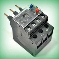 Thermal relay for an electric motor: operating principle, device, how to choose
 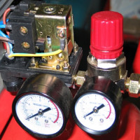 Pressure switch for compressor: device, marking + wiring diagram and adjustment
 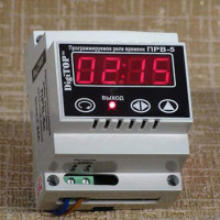 Time relay: operating principle, wiring diagram and tuning recommendations
  Voltage control relays: operating principle, circuit, connection nuances
  Intermediate relay: how it works, labeling and types, nuances of adjustment and connection
  How much does it cost to connect gas to a private house: the price of organizing gas supply
  The best washing machines with dryer: model rating and customer tips
  What is the color temperature of light and the nuances of choosing the temperature of the lamps to suit your needs
  Replacement of a geyser in an apartment: replacement paperwork + basic norms and requirements
If you have ever tried to repair a modern electric kettle, then you certainly have encountered a thermal relay. Most often the malfunction is in it. The contacts burn up, the resistance increases and the relay starts to warm up. The contact plate melts the plastic base and freezes in it. There is only one option - replacing the entire relay. Otherwise, the kettle will not turn on.
Everything is very clear, affordable. Studying as an electrician, this entry really helped to write a diploma on this topic. Many thanks to you author.