Thermal relay for an electric motor: operating principle, device, how to choose

During the operation of power equipment, it is constantly affected by current overloads, which reduce durability. Protection in such situations is a thermal relay for the electric motor, which cuts off power supply in the event of unusual circumstances.
We offer to understand the design, principle of operation, types and nuances of connecting protective devices. In addition, we will tell you what parameters and characteristics should be considered when choosing a thermal relay.
The content of the article:
Thermal relay design
Thermal relays of all kinds have a similar device. The most important element of any of them is a sensitive bimetal plate.
The value of the tripping current is influenced by the temperature indicators of the medium in which the relay operates. An increase in temperature reduces the response time.
To minimize this effect, device developers choose the highest possible temperature of bimetal. For the same purpose, some relays provide an additional compensation plate.

If nichrome heaters are included in the design of the relay, they are connected in parallel, serial or parallel-serial circuit with a plate.
The current value in the bimetal is regulated using shunts. All parts are mounted in the housing. U-shaped bimetallic element is fixed on the axis.
The coil spring abuts against one end of the plate. The other end is based on a balanced insulating block. It makes rotations around the axis and is a support for the contact bridge equipped with silver contacts.
To coordinate the setpoint current, the bimetallic plate is connected with its left end to its mechanism. Adjustment occurs due to the effect on the primary deformation of the plate.
If the magnitude of the overload currents becomes equal to or greater than the settings, the insulation block rotates under the influence of the plate. During its overturning, the disconnecting contact of the device is disconnected.

Automatically, the relay makes a reset. The self-return process takes no more than 3 minutes from the moment the protection is turned on. Manual reset is also possible, for this a special Reset key is provided.
When using it, the device takes its initial position in 1 minute. To activate the button, it is rotated counterclockwise until it rises above the body. The installation current is usually indicated on the panel.
The principle of operation of the device
Performing a protective function, circuit breaker disconnects power supply circuits. The thermal relay differs from it in that when the load is exceeded, it simply issues a control signal. With this protection, small currents are switched in the same control circuit.
In the circuit before the thermal relay is magnetic switch. When the circuits open in an emergency, there is no need for duplication of the contactor. Therefore, no material is used for the manufacture of power contact groups.
The most popular are instruments equipped with bimetallic plates. The plate itself consists of two similar elements.
One of them has a significant temperature coefficient, and the other is slightly lower. These two components fit snugly together.

Such a rigid bond is ensured by welding or hot rolling. Due to the fact that the plate is fixed motionless, when heated, its bending towards the element with a lower temperature coefficient is observed. This principle is taken as a basis when creating thermal relays.
In their production, chromium-nickel steel and non-magnetic are used, which have a large temperature coefficient. As a material with a small value of this parameter, Invar is used - a compound of nickel with iron.

A plate of bimetal is heated load currents. They flow most often through a special heater. There is also combined heating, in which, in addition to the heat given off by the heater, bimetal also heats the current passing through it.
How to connect a thermal relay
A closed contact (normal connected), by means of which the thermal module is connected to a magnetic starter, is designated NC or NC, which stands for normally closed. The letter combination NO indicates a normally open contact.
In a simple circuit, it is used to give a signal indicating that the motor protection has been triggered due to exceeding the threshold temperature.
When implemented in complex control circuits, it is capable of generating in an emergency order a signal for removing the conveyor from the operating state.

The designation of the terminals of the contactors dictates GOST: normally closed - 95-96, normally open - 97-98. A starter is connected to the first pair, the second is used for signaling circuits.Since the motor and thermal relay must be protected against short circuit, the circuit must contain a circuit breaker.
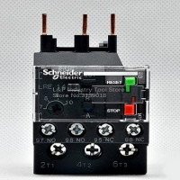
The device diagram includes the “Test” and “Stop” or “Reset” buttons. Using the first, they check the operability, and the second - manually disable the protection.
With the help of the rotary cocking switch, after the protection is turned on, the electric motor is restarted. The glass cover of the product is marked and sealed.
Based on the type of connection, two large groups of thermal relays can be distinguished:
- first group - devices mounted behind a magnetic starter and those connected using jumpers;
- second group - devices installed directly on the contactor of the starter.
In the latter case, at startup, the main load falls on the contactor. Here, the thermal module is equipped with copper contacts connected directly to the starter inputs.

To TR connect wires from the engine. The relay itself in such a circuit represents an intermediate unit that analyzes the current flowing in transit to the engine from the magnetic starter.
Nuances when installing the device
Not only current overloads, but also indicators of external temperature can affect the response speed of the thermal module. Protection will work even in the absence of overload.
It also happens that under the influence of forced ventilation the engine is subject to thermal overload, but the protection does not work.
To avoid such phenomena, you need to follow the recommendations of specialists:
- When choosing a relay, focus on the maximum permissible operating temperature.
- Mount the protection in one room with the protected object.
- For installation, select places where there are no heat sources or ventilation devices.
- It is necessary to adjust the thermal module, focusing on the actual ambient temperature.
- The best option is the presence of built-in thermal compensation in the design of the relay.
An additional option of the thermal relay is protection in the event of a phase failure or a completely power supply network. For three-phase motors, this moment is especially relevant.

If there is a malfunction in one phase, the other two take on a larger current. As a result, overheating quickly occurs, and then shutdown. If the relay fails, both the motor and the wiring can fail.
Existing device types
The class of thermal relays includes several types: TRN, RTL, TRP, RTI, PTT. The use of each is due to design features.
Two-phase current relay (TRN), used mainly for electrical protection of induction motors with squirrel-cage rotor. As a rule, they operate from a network with a rating of up to 500 V, a frequency of 50 Hz.
The relay is equipped with a manual contact control mechanism. The dimensions of the TRN make it possible to integrate them into complete devices of both closed and open type stations coordinating the operation of drives. They do not perform the short-circuit protection function and themselves need it.
TRP relay have a vibration resistant mechanism, shockproof housing. Designed for the protection of asynchronous three-phase motors operating in conditions of high mechanical loads.
They are designed for a maximum current of 600 A and a voltage of maximum 500 V, and in DC circuits - 440 V. The automation is insensitive to external temperature and is triggered when the indicator exceeds 200 ° C.
RTL devices - three-phase, in addition to protecting the engine from overloads, protect the rotor from jamming. They insure it against breakdowns in case of phase imbalance, with a prolonged start-up.
They work autonomously with the KRL terminal blocks and in the modification with the PML magnetic starter. The current working interval is from 0.10 to 86 A.

PTT - the device protects induction motors from current surges, phase imbalance, jamming and other emergency situations. It is used both as an independent device and as an installation in PMA and PME starters.
Product three-phase RTI endowed with the same functions as the previous one, but is used in the modification with KTM and KMI starters.
How to choose a thermal relay
An engine needs a relay for protection when, for technological reasons, there is a potential threat of congestion. The second case is the need to limit the start time in low voltage conditions.
These requirements are contained in the relevant instructions. Which sets out the wish to equip the protective product with a time delay. They realize all this with the help of thermal relays.
Basic characteristics of devices
The basic data of the device protecting the engine are:
- Contact performance depending on current parameters - time-current indicator.
- The operating current at which the TP is triggered.
- Current limit settings. In all devices manufactured by different manufacturers, this parameter differs slightly. Exceeding the nominal by 20% entails the operation of the device in about 25 minutes.
- Rated current of a working bimetallic plate. This refers to a value above which the relay does not turn off immediately.
- The current range in which the relay is triggered.
Information about the thermal relay can be obtained by decoding its markings. The symbol for the type of performance may vary.

The location of domestic TPs is regulated by GOST 15150. Their work is influenced by such moments as the height of rise above sea level, vibration, shock, acceleration.
Manufacturers reflect all these nuances in the labeling of their products. Some of them additionally include information on the possibility of working in the presence of harmful substances and explosive gases.
Choosing a device by the rules
The requirements for the thermal relay are set out in the instructions. It is also stipulated here that the protection must have a time delay. They realize all the requests using special devices.

When analyzing the time-current characteristics of a TR, one must take into account that the operation can occur from an overheated or cold state.
Impeccable protection assumes that the curve depicting the optimal for the trouble-free operation of the equipment dependence of the duration of the current flow on the current value for the relay and motor are different. The first should be lower than the second.

The correct selection of the protective product is based on such a parameter as the operating rated current. Its value is related to the rated load current of the electric motor.
Both international and domestic standards stipulate that the rated current of the motor is similar to the setting of the thermal relay trip current.
This means that the inclusion in the operation of the device occurs with an overload of 20 to 30% or with Iav.x1.2 or 1.3 no later than 20 minutes.
Proceeding from this, the choice must be made so that the failure current of the TR exceeds the rated current of the covered object by an average of 12%. The value of In is displayed in the passport of the device and on the plate mounted on the housing.
Based on it, they select both the TR and the starter corresponding to it. The relay scale is calibrated in amperes and, as a rule, corresponds to the set current value.
An example is the selection of a thermal relay for an induction motor connected to a 380 V network with a power of 1.5 kW.
The working rated current for it is 2.8 A, which means that the threshold current for the thermal relay will be: 1.2 * 2.8 = 3.36 A. According to the table, the selection must be stopped at RTL-1008, whose adjustment range is in limits from 2.4 to 4 A.

When the motor nameplate data is not known, the current is determined by using special devices - clamp meters or a multimeter with the corresponding option. Measurements are carried out on each of the phases.
It is important when choosing to pay attention to the voltage indicated on the device. If you plan to use the tandem TP starter, you need to consider the number of contacts.
When connecting the device to a three-phase network, a module is required that has a protection function for cases of burnout of conductors or phase imbalance.
Conclusions and useful video on the topic
Scheme of effective engine protection:
Components of a thermal relay:
The principle of interaction of various devices in different options for connecting a thermal relay is the same. For better orientation in the circuits, one must be able to “read” the device markings. Ideally, all work on the connection should be performed by a master who has permission to work in high voltage conditions.
Is there anything to supplement, or have questions about the selection and use of a thermal relay? You can leave comments on the publication, participate in discussions and share your own experience in using devices. The contact form is located in the lower block.
 Thermal relay: operating principle, types, connection diagram + adjustment and marking
  Phase control relays: operating principle, types, marking + how to adjust and connect
  Time relay: operating principle, wiring diagram and tuning recommendations
  Voltage control relays: operating principle, circuit, connection nuances
 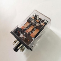 Electromagnetic relay: device, marking, types + subtleties of connection and adjustment
  Pressure switch for compressor: device, marking + wiring diagram and adjustment
  How much does it cost to connect gas to a private house: the price of organizing gas supply
  The best washing machines with dryer: model rating and customer tips
  What is the color temperature of light and the nuances of choosing the temperature of the lamps to suit your needs
  Replacement of a geyser in an apartment: replacement paperwork + basic norms and requirements