Pulse relay for lighting control: how it works, types, labeling and connection

To meet the modern requirements of lighting apartments, office premises and enterprises, complex electrification systems are used. When designing them to solve certain problems, a number of equipment is used, which is constantly being improved.
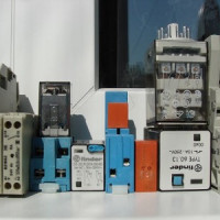
So, a pulse relay for controlling lighting from several places has been used relatively recently. Gradually, it displaces standard circuits with passage switches.
The content of the article:
Where can a pulse relay be used?
The introduction of this device in domestic use is due to simple convenience. After all, it allows you to control lighting from at least two points.
In an apartment, it can be a bedroom, where switching on happened at the entrance, and turning off next to the bed. In offices, these are long corridors, flights of stairs and large conference rooms.

With the task of three-position control, walk-through and cross circuit breakers. This scheme is still widely used. But there are obvious flaws in it.
Firstly, it is a system that is quite complicated for installation, in which electricity passes through the main circuit breaker, junction box, the switches themselves and then to the lighting lamps. When installing it, errors often occur. If more than three control places are necessary, then the scheme is complicated.

Secondly, all wires have the same cross-section, since they use the current of the same voltage, which affects the total cost. They also include the price of passage switches, several times higher than the cost of conventional ones.
But the need to use a pulse relay is not only for reasons of comfort. It is also used for signaling and protection.
For example, in an industrial enterprise, to start production processes requiring high electrical power, this device allows you to protect the operator. Since it works from low-voltage currents or is completely controlled remotely.
Device and principle of operation
In the general sense of the word, a relay is an electrical engineering mechanism that closes or breaks an electrical circuit based on certain electrical or other parameters that affect it.
Its non-switching design was invented back in 1831 by J. Henry. And two years later they began to use S. Morse to ensure the functioning of the telegraph.
Two main groups can be distinguished: electromechanical and electronic. In the first type of device, the work is carried out by the mechanism, and in the second, the circuit board with the microcontroller is responsible for everything. It is convenient to consider his work on the example of an electromechanical relay, which is a pulse.

Structurally, it can be represented as follows:
- Coil - This is a copper wire wound on a base of non-magnetic material. It can be in fabric insulation or varnished without electricity.
- Corecontaining iron and coming into action when passing electric current through the turns of the coil.
- Movable anchor - This is a plate that is attached to the anchor and affects the make contacts.
- Contact system - directly circuit status switch.
The relay is based on the phenomenon of electromagnetic force. It appears in the ferromagnetic core of the coil when current flows through it. The coil in this case is a retractor.
The core in it is connected with a movable anchor, which drives the power contacts, carrying out switching. They can be normally open / normally closed. Sometimes a contact block can contain both open and closed connection types.

An additional resistor can be connected to the coil, which increases the accuracy of operation, as well as a semiconductor diode, which limits the overvoltage on the winding. In addition, a capacitor mounted parallel to the contacts may be present in the design to reduce arcing.
You can imagine the operation of the device more clearly by breaking it into several blocks:
- performing - this is a contact group that closes / opens the electric circuit;
- intermediate - a coil, a core and a movable anchor engage a performing unit;
- manager - in this relay converts an electrical signal into a magnetic field.
Since a one-time electrical pulse is needed to switch the position of the contacts, it can be concluded that these devices consume voltage only at the time of switching. This significantly saves energy, unlike conventional walk-through switches.
The second type of pulse relay is an electronic type. The microcontroller is responsible for the work in it. An intermediate unit here is a coil or a semiconductor switch. The use of elements such as programmable logic controllers in the circuit allows you to supplement the relay, for example, with a timer.

Species, Labeling and Benefits
The main types of pulse relays are electromechanical and electronic. Electromechanical in turn are classified according to the principle of action.
Varieties of pulse devices
This means that the switching of power contacts can be carried out by forces other than the efforts of the magnet.
They are divided into:
- electromagnetic;
- induction;
- magnetoelectric;
- electrodynamic.
Electromagnetic devices in automation systems are used more often than others. They are quite reliable due to the simple method of operation, based on the action of electromagnetic forces in the ferromagnetic core, provided that there is current in the coil.
Contact Impact electromagnetic relays carries out the frame, which in one position is attracted by the core, and returns to the second by a spring.

Induction ones have an operating principle based on the contact of currents - alternating with induced magnetic fluxes with the fluxes themselves. This interaction creates a torque that drives a copper disk located between two electromagnets. Rotating, it closes and opens the contacts.
The work of magnetoelectric devices is performed due to the interaction of the current in the rotary frame with a magnetic field created by a permanent magnet. The control of the closing / breaking of the contacts is due to its rotation.
Relative to their type, such relays are very sensitive. However, they were not widely used due to the response time of 0.1-0.2 s, which is considered long.
Electrodynamic relays operate due to the force arising between the moving and fixed current coils. The contact closure method is the same as in the magnetoelectric device. The only difference is that induction in the working gap is created by the electromagnetic method.
Electronic models are structurally nearly identical to electromechanical ones. They have the same blocks: executing, intermediate and managing. The difference lies only in the latter. Switching control is carried out by a semiconductor diode as part of a microcontroller on a printed circuit board.

This type of relay is equipped with additional modules. For example, a timer allows you to run a lighting control program after a specified period of time. This is convenient for saving energy when equipment is not needed. If necessary, turn off the light by double-clicking the button.
Advantages and disadvantages of the main types of relays
Different from semiconductor switches, electromechanical switches have the following advantages:
- Relatively low cost due to inexpensive components.
- The formation of a small amount of heat at the switched on contacts due to a weak voltage drop.
- The presence of powerful insulation of 5 kV between the coil and the contact group.
- No exposure to the harmful effects of overvoltage pulses, interference from lightning, switching processes of powerful electrical installations.
- Management of lines with a load of up to 0.4 kV with a small volume of the device.
When a circuit is closed with a current of 10 A in a small-volume relay, less than 0.5 W is distributed over the coil. While, on electronic counterparts, this figure can be more than 15 watts. Due to this, there is no problem of cooling and harm to the atmosphere.
Their disadvantages include:
- Depreciation and problems when switching inductive loads and high voltage with direct current.
- Turning the circuit on and off is accompanied by radio interference.This requires shielding or an increase in the distance to the equipment subject to interference.
- Relatively long response time.
Another disadvantage is the presence of continuous mechanical and electrical wear during switching. These include oxidation of contacts and their damage from spark discharges, deformation of spring blocks.

Unlike electromechanical, electronic relays control the intermediate unit through a microcontroller.
The advantages and disadvantages of electronics can be disassembled by the example of F&F devices relative to the ABB brand, which produces mechanics.
Of the advantages of the first type of switches, we can distinguish:
- greater security;
- high switching speed;
- market availability;
- indicator alerts about the operating mode;
- advanced functionality;
- silent work.
In addition, the indisputable advantage lies in several installation options - it is possible to install not only on the DIN rail panel, but also in undergrowth.
Cons of F&F electronics compared to ABB mechanics:
- disruption in case of power outages;
- overheating when switching high currents;
- "glitches" are possible for no apparent reason;
- turning off the device during a short-term power off;
- high resistance in the closed position;
- some relays operate only on direct current;
- The semiconductor circuit does not immediately pass current back to the normal direction.
Despite these shortcomings, electronic switches are constantly evolving, and due to the greater functional potential relative to electromechanical ones, their predominant use is expected.

The main characterizing parameters
Depending on the purpose and scope of the relay can be classified according to several criteria:
- return coefficient - the ratio of the output current of the armature to the current retraction;
- output current - its maximum value in the clamps of the coil at the exit of the armature;
- retraction current - its minimum indicator in the clamps of the coil when the armature returns to its original position;
- set point - the level of the response value within the specified limits set in the relay;
- response value - value of the input signal to which the device automatically responds;
- nominal valuesI - voltage, current, and other values underlying the operation of the relay.
Also, electromagnetic devices can be divided by the response time. The longest delay for a time relay is more than 1 second, with the ability to configure this parameter. Then there are slower ones - 0.15 seconds., Normal - 0.05 seconds., High-speed - 0.05 seconds. And the fastest inertialess - less than 0.001 seconds.
Decoding of product labeling
The contactor marking code can often be found in store catalogs and on the device itself. It gives a complete description of the design features, purpose and conditions of their use.
The designation of the designation can be disassembled on the electromagnetic intermediate relay REP-26. It is used in AC circuits up to 380 V and DC up to 220 V.

The product designation in the store may look like this: REP 26-004A526042-40UHL4.
REP 26 - ХХХ Х Х ХХ ХХ Х - 40ХХХ4. This type of designation can be disassembled as follows:
- 26 - series number;
- ХХХ - type of contacts and their number;
- X - switching wear resistance class;
- X - type of switching coil, type of relay return and current type;
- XX - design according to the method of installation and connection of conductors;
- XX - value of current or voltage of the coil;
- X - additional structural elements;
- 40 - protection level of IP or GOST14254 standard;
- ХХХ4 - climatic zone of application in accordance with GOST 15150.
Climatic modification can be: UHL - for cold and temperate climate, or О - for tropical or general climatic modification.
According to special designation tables, the device in question is a electromagnetic intermediate relay, with four switching contacts, switching resistance class A, using direct current. It has a socket outlet with lamellas for soldering external conductors, a 24 V coil and a manual manipulator.
Several types of wiring diagrams
There are several installation options, each of which has its own characteristics, advantages and disadvantages.
The designation of the relay contacts RIO-1 has the following decoding:
- N - zero wire;
- Y1 - input enable;
- Y2 - input off;
- Y - input on and off;
- 11-14 - switching contacts of the normally open type.
These designations are used on most relay models, but before connecting to the circuit, you should additionally familiarize yourself with them in the product passport.

In this circuit, the relay power contacts use a current of 16 A. Protection of control circuits and lighting systems carried out by a 10 A circuit breaker. Consequently, the wires have a diameter of at least 1.5 mm2.
The connection of the push-button switches is made in parallel. The red wire is the phase, it goes through all three push-button switches to the power contact 11. The orange wire is the switching phase, it comes to input Y. Then it leaves terminal 14 and goes to the bulbs. The neutral wire from the bus is connected to terminal N and to the luminaires.
If the light was initially turned on, then when you press any switch, the light will turn off - there will be a short-term switching of the phase wire to terminal Y and contacts 11-14 will open. The same thing will happen the next time you press any other switch. But pins 11-14 will change position and the light will turn on.
The advantage of the above circuit over walk-through and cross-circuit breakers is obvious. However, with a short circuit, the detection of damage will cause some difficulties, unlike the following option.

This is a less common connection option. It is the same as the previous one, but the control and lighting circuits have their own circuit breakers for 6 and 10 A, respectively. This makes troubleshooting easier.
If it becomes necessary to control several lighting groups by a separate relay, the circuit is somewhat modified.

Another option for using pulse relays is a centrally controlled system.

Two circuit breakers are added to this circuit to close and open the circuit. The first button can only turn on the lighting group. In this case, the phase from the ON switch will come to terminals Y1 of each relay and contacts 11-14 will be closed.
The opening switch works similarly to the first switch. But switching is carried out on the Y2 terminals of each switch and its contacts occupy the open circuit position.
Conclusions and useful video on the topic
The video material tells about the device, work, application and the history of the creation of this type of device:
The following plot describes in detail the principle of operation of solid state or electronic relays:
The use of pulse relays is increasingly used in modern electrification systems. Increasing requirements for the functionality and flexibility of lighting control, material saving and safety creates a continuous impulse to improve contactors.
They are reduced in size, simplified structurally, increasing reliability. And the use of fundamentally new technologies at the heart of the work allows them to be used in harsh conditions of dusty production, vibration, magnetic fields and humidity.
Please write comments in the block below. Ask questions, share useful information on the topic of the article, which is useful to site visitors. Tell us about how to choose and install a pulse switch.
 Intermediate relay: how it works, labeling and types, nuances of adjustment and connection
 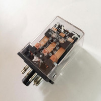 Electromagnetic relay: device, marking, types + subtleties of connection and adjustment
  Thermal relay: operating principle, types, connection diagram + adjustment and marking
  Phase control relays: operating principle, types, marking + how to adjust and connect
  Pressure switch for compressor: device, marking + wiring diagram and adjustment
  Solid State Relays: Types, Practical Applications, Wiring Diagrams
  How much does it cost to connect gas to a private house: the price of organizing gas supply
  The best washing machines with dryer: model rating and customer tips
  What is the color temperature of light and the nuances of choosing the temperature of the lamps to suit your needs
  Replacement of a geyser in an apartment: replacement paperwork + basic norms and requirements