380V electromagnetic starter: device, connection rules and selection recommendations

An electromagnetic starter is a device that very often is an integral part of electrical circuits. As a rule, a 380V three-phase electromagnetic starter is used in electric motor control circuits. However, in addition to switching electric motor circuits, this same element can be successfully used for other purposes.
Consider a typical device and the principle of operation of an electrical appliance. In addition, we outline the selection criteria for the starter, decipher its labeling and describe the nuances of connecting the EMF to the electrical circuit.
The content of the article:
EMF design features
The design of the electromagnetic starter (EMF) does not differ in high complexity. But this factor does not reduce the reliability of the device.
How does this device work?
The reliability criterion, for the most part, is established by the correct connection of the circuits and the exact selection of the load.
If these criteria are met, the device in most cases operates flawlessly for a long time.

Classical performance includes the following elements:
- The case is folding from two halves.
- Inductor.
- Magnetic circuit.
- Switching movable chassis.
- A group of core contacts.
- Group of auxiliary contacts.
The element of the magnetic starter responsible for organizing the switching of the power circuit is a movable chassis combined with one part of the (mobile) magnetic circuit.
The chassis itself is made of dielectric material, and metal (brass) plates are used as make contacts. At the ends of the plates are contact patch made of refractory metals, usually an alloy of silver.

The fixed part of the magnetic circuit is firmly fixed inside the second half of the body of the electromagnetic starter. An inductor is put on this part of the magnetic circuit and a return spring is installed.
The second part of the device housing is also provided with contacts of the power and auxiliary groups. These contacts are fixed to the housing with screws.

The device of a standard magnetic starter involves the union of two halves of the housing, as a result of which the two halves of the W-shaped magnetic circuit are also combined into a single design.
At the same time, due to the return spring, a small gap remains between the halves of the magnetic circuit, the main contact groups in this position remain broken.
EMF principle of operation
The principle of operation of the device is based on the effect of electromagnetic induction. If there is no voltage on the coil located inside the starter, the magnetic core remains in the “with a gap” position, the main contacts are broken.

When an electric current is passed through the coil, under the influence of a magnetic field, the second (moving) part of the magnetic circuit overcomes the force of the spring and is attracted to the first (fixed) part.
Accordingly, the main contact groups of the starter are closed by the plates of the movable chassis.
The reverse process is obvious - when the voltage is removed from the terminals of the inductor, the magnetic field ceases to act, under the force of the return spring, the movable chassis and the second part of the magnetic circuit are repelled. Accordingly, the magnetic starter returns to the contact breaking state.

It should be noted - based on the configuration of the appliance, the contact group diagram can have a very different structure. Especially regarding auxiliary contacts, which can be in a closed or open state as opposed to the state of the main contacts of the device.
A feature of modern designs of magnetic starters is the modernization of the control circuit of the inductor.
If the execution of the old "obsolete" devices assumed direct supply of voltage to the coil, taken from one of the phases, now electronic circuits are increasingly used.

So, for example, products of a well-known company "ABB" equipped with an electronic circuit for stabilizing the voltage supplied to the terminal of the inductor of the magnetic starter.
The control of the coil through the electronic circuit is characterized by the fact that the alternating voltage is pre-rectified and then a pulse signal is formed. This approach provides increased service life and improved stability of action.
How to choose the right electromagnetic starter
Given the somewhat wide range of products of this kind that is present on the commercial market, the selection rules are more than relevant for the end user.
Instrument Technical Parameters
The exact and correct choice of a magnetic starter for 380 volts, for example, for an electric motor, will ensure uninterrupted operation of the motor, and most importantly, the safety of the electrical system.

A specific device is selected, of course, based on the technical and operational parameters of the load expected to be connected. Significant influence on the right choice has the product belonging to a particular brand.
It should be noted that there is a rather high percentage of low quality products on the market. Therefore, the brand, in this case, is an important selection criterion.
Marking and type of fastening of products
Each device, in any case, branded, has the corresponding marking directly on the case. Based on the technical information contained in the marking, it is enough to simply select a switching device in exact accordance with the required parameters.

So, switching devices of the same company "ABB" have approximately the following marking system:
A-26-30-10
The encoding string is decrypted as follows:
- «AND" - the letter designation indicates the type of device;
- «26» - the second digital marker determines the rated current in amperes;
- «30» - the third designation indicates the number of power contacts;
- «10» - the last number characterizes the number of auxiliary contacts.
Moreover, for the last two positions of the list, the separation of numbers is characteristic. That is, if the number “30” is indicated, it means the presence of three (3) normally open contacts and the absence of (0) normally closed contacts.
A similar decoding for the digital code (10), indicating additional contact groups.

When choosing the performance of a magnetic starter for 380V for appropriate purposes, you should pay attention to the mounting technique of the device.
As a rule, a significant proportion of devices of a modern configuration are carried out taking into account the installation on a DIN rail. But there are also designs of devices for fastening in the traditional way - with screws.
The nuances of connecting the EMF as part of the circuit
Classic EMF connection diagram It does not stand out with special difficulties. In fact, if you do not take into account auxiliary contact groups, you need to connect three main lines - there are three phases in the 380 volt circuit.
In total, these are 6 contacts - three input and three output, plus two contacts of the inductor circuit.

However, the actual inclusion in the electric circuit is often accompanied by a rather complicated circuit, where a large number of auxiliary contacts are involved.
As a rule, modern schemes for switching on the same electric motors require an additional input of protection devices - thermal relay other.

When connecting circuits to an EMF rated for 380V, the following rules should be followed:
- connect in the absence of voltage;
- input circuits connect through circuit breaker;
- use a wire cross section that is optimally suited to the contact;
- tighten the screws all the way, but without using excessive force;
- check the integrity of the coil winding (ohmmeter) before connecting the power line;
- Check the master course of the moving chassis after all connections have been completed.
Typically, switching devices of this type are installed inside a cabinet designed for the installation of electrical lines. Cabinet design - with a door for ease of maintenance and restrict access for unauthorized persons.
Conclusions and useful video on the topic
A full-fledged informative layout of the magnetic starter through a video recorded by a well-known trading company of electronic components.
The author of the video reveals in detail and in an accessible form the essence of the switching device:
Switching devices, such as an electromagnetic starter for three-phase networks, are used in industrial, economic and household applications quite often. Therefore, it is useful to study information on such devices in a timely manner - how to work with them, how to connect, how to determine for installation, etc.
Is there anything to supplement, or have questions about choosing and connecting an electromagnetic starter? You can leave comments on the publication, participate in discussions and share your own experience using such devices. The contact form is located in the lower block.
 Time relay: operating principle, wiring diagram and tuning recommendations
  Electromagnetic relay: device, marking, types + subtleties of connection and adjustment
 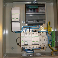 Connection diagrams of magnetic starter for 220 V and 380 V + features for independent connection
  Limit switch: what is it, marking + connection rules
  Pressure switch for compressor: device, marking + wiring diagram and adjustment
  Intermediate relay: how it works, labeling and types, nuances of adjustment and connection
  How much does it cost to connect gas to a private house: the price of organizing gas supply
  The best washing machines with dryer: model rating and customer tips
  What is the color temperature of light and the nuances of choosing the temperature of the lamps to suit your needs
  Replacement of a geyser in an apartment: replacement paperwork + basic norms and requirements
Connecting a magnetic starter is another story. Even using the classic circuit, you can easily make a mistake, forgetting, for example, the nominal value of the inductor. For some reason, everyone believes that it is standard at 230 volts and is connected, respectively, to the neutral and to one of the phases. But I also had to deal with the 400-volt version, in which case its conclusions must be connected to various phases (through a series of buttons, of course). And sometimes there are exotic voltage ratings of the coil, say 110 or 36 volts. So before connecting, do not forget to ask about this parameter.
Good afternoon, Gleb. The probability of error is reduced if the electrician uses the design switching scheme, simultaneously checking the characteristics laid down by the designers, with the passport data of the real equipment proposed by the customer.
Your statement - "Everyone ... believes that it is ... at 230 volts" - is erroneous and characterizes the qualifications of your environment. By the way, the “exotic” voltages used to power the control coils (you mistakenly call them inductors) are much more (attached screenshot).