Electromagnetic relay: device, marking, types + subtleties of connection and adjustment

The conversion of electrical signals into the corresponding physical quantity - motion, force, sound, etc., is carried out using drives. The drive should be classified as a converter, since this device changes one type of physical quantity into another.
The drive is usually activated or controlled by a low voltage command signal. It is additionally classified as a binary or continuous device based on the number of stable states. So, the electromagnetic relay is a binary drive, given the two existing stable conditions: on - off.
In the presented article, the principles of the operation of the electromagnetic relay and the scope of the use of devices are discussed in detail.
The content of the article:
Drive Basics
The term "relay" is characteristic of devices that provide an electrical connection between two or more points through a control signal.
The most common and widely used type of electromagnetic relay (EMR) is the electromechanical design.

The fundamental control scheme for any equipment always provides the ability to enable and disable. The easiest way to complete these steps is to use the power lock switch.
Manual action switches can be used for control, but have disadvantages. Their obvious drawback is the setting of the states “on” or “disabled” physically, that is, manually.
Manual switching devices, as a rule, are large-sized, delayed-action devices capable of switching small currents.

Meanwhile, electromagnetic relays are mainly represented by electrically controlled switches. Devices have different shapes, dimensions and are divided by the level of rated power. The possibilities of their application are extensive.
Such devices, equipped with one or more pairs of contacts, can be included in a single design of larger power actuators - contactors, which are used for switching mains voltage or high-voltage devices.
Fundamental principles of the work of EMR
Traditionally, electromagnetic type relays are used as part of electrical (electronic) switching control circuits. At the same time, they are installed either directly on the printed circuit boards, or in the free position.
General structure of the device
The load currents of the products used are usually measured from fractions of an ampere to 20 A or more. Relay circuits are widespread in electronic practice.

The design of the electromagnetic relay converts the magnetic flux generated by the applied AC / DC voltage into mechanical force. Thanks to the obtained mechanical force, the contact group is controlled.
The most common design is the shape of the product, including the following components:
- exciting coil;
- steel core;
- basic chassis;
- contact group.
The steel core has a fixed part called a rocker arm and a movable spring-loaded part called an anchor.
In fact, the anchor supplements the magnetic field circuit, closing the air gap between the stationary electric coil and the moving armature.

The armature moves on hinges or rotates freely under the action of the generated magnetic field. This closes the electrical contacts attached to the valve.
As a rule, the return spring (s) located between the beam and the armature returns the contacts to their original position when the relay coil is de-energized.
The action of the relay electromagnetic system
The simple classical design of EMF has two sets of electrically conductive contacts.
Based on this, two states of the contact group are realized:
- Normally open contact.
- Normally closed contact.
Accordingly, a pair of contacts is classified as normally open (NO) or, being in a different state, normally closed (NC).
For relays with normally open position of the contacts, the state "closed" is achieved only when the excitation current passes through the inductive coil.

In another embodiment, the normally closed position of the contacts remains constant when the excitation current is absent in the coil circuit. That is, the contacts of the switch return to their normal closed position.
Therefore, the terms “normally open” and “normally closed” should refer to the state of electrical contacts when the relay coil is de-energized, that is, the voltage of the relay is disconnected.
Electrical relay contact groups
Relay contacts are usually represented by electrically conductive metal elements that are in contact with each other, close the circuit, acting similarly to a simple switch.
When the contacts are open, the resistance between normally open contacts is measured by a high value in megaohms. This creates an open circuit condition when the passage of current in the coil circuit is excluded.

If the contacts are closed, the contact resistance should theoretically be zero - the result of a short circuit.
However, this condition is not always noted. The contact group of each individual relay has a certain contact resistance in the "closed" state. Such resistance is called sustainable.
Features of the passage of load currents
For the practice of installing a new electromagnetic relay, the contact resistance of the inclusion is noted to be small, usually less than 0.2 ohms.
The reason is simple: the new tips remain clean so far, but over time, the resistance of the tip will inevitably increase.
For example, for contacts under a current of 10 A, the voltage drop will be 0.2x10 = 2 volts (Ohm's law). It turns out that if the supply voltage supplied to the contact group is 12 volts, then the voltage for the load will be 10 volts (12-2).
When contact metal tips wear out, not being adequately protected from high inductive or capacitive loads, damage from the effect of an electric arc becomes inevitable.

An electric arc — sparking at the contacts — leads to an increase in the contact resistance of the tips and, as a result, to physical damage.
If you continue to use the relay in this state, the contact tips can completely lose the physical property of the contact.
But there is a more serious factor when, as a result of damage by an arc, the contacts eventually weld, creating a short circuit condition.
In such situations, the risk of damage to the circuit controlled by the EMI is not excluded.
So, if the contact resistance increased by 1 ohm from the influence of the electric arc, the voltage drop across the contacts for the same load current increases to 1 × 10 = 10 volts DC.
Here, the magnitude of the voltage drop across the contacts may not be acceptable for the load circuit, especially when working with 12-24 V supply voltages.
Type of relay contact material
In order to reduce the influence of the electric arc and high resistances, the contact tips of modern electromechanical relays are made or coated with various silver-based alloys.
In this way, it is possible to significantly extend the life of the contact group.

In practice, the use of the following materials is noted, with which the tips of contact groups of electromagnetic (electromechanical) relays are processed:
- Ag is silver;
- AgCu - silver-copper;
- AgCdO - silver-cadmium oxide;
- AgW - silver-tungsten;
- AgNi - silver-nickel;
- AgPd - silver-palladium.
Increasing the service life of the tips of the contact groups of the relay by reducing the number of formations of the electric arc is achieved by connecting resistive-capacitor filters, also called RC dampers.
These electronic circuits are connected in parallel with the contact groups of electromechanical relays. The voltage peak, which is observed at the moment of opening the contacts, with this solution is seen to be safely short.
Using RC dampers, it is possible to suppress the electric arc that forms on the contact tips.
Typical EMR contact design
In addition to the classic normally open (NO) and normally closed (NC) contacts, the mechanics of relay switching also require classification based on the action.
Features of the execution of the connecting elements
The electromagnetic relay designs in this embodiment allow one or more separate switch contacts.

The execution of contacts is characterized by the following set of abbreviations:
- SPST (Single Pole Single Throw) - unipolar unidirectional;
- SPDT (Single Pole Double Throw) - unipolar bidirectional;
- DPST (Double Pole Single Throw) - bipolar unidirectional;
- DPDT (Double Pole Double Throw) - bipolar bidirectional.
Each such connecting element is referred to as a “pole”. Any of them can be connected or reset, while simultaneously activating the relay coil.
Subtleties of the use of devices
Despite the simplicity of the design of electromagnetic switches, there are some subtleties of the practice of using these devices.
So, experts categorically do not recommend connecting all relay contacts in parallel in order to commute the load circuit with high current in this way.
For example, connect a load of 10 A by parallel connection of two contacts, each of which is designed for a current of 5 A.
These subtleties of installation are due to the fact that the contacts of mechanical relays never close or open at a single point in time.
As a result, one of the contacts will be overloaded in any case. And even taking into account the short-term overload, premature failure of the device in such a connection is inevitable.

Electromagnetic products can be used as part of electrical or electronic circuits with low energy consumption as switches for relatively high currents and voltages.
However, it is categorically not recommended to pass different load voltages through the adjacent contacts of the same device.
For example, switch AC voltage of 220 V and DC 24 V. Always use separate products for each option in order to ensure safety.
Reverse Voltage Protection Techniques
An important part of any electromechanical relay is a coil. This part relates to a high inductance load category because it has wire winding.
Any wire-wound coil has some impedance consisting of the inductance L and resistance R, thus forming a series circuit LR.
As current flows through the coil, an external magnetic field is created. When the current flow in the coil stops in the “off” mode, the magnetic flux (transformation theory) increases and a high reverse voltage EMF (electromotive force) occurs.
This induced value of the reverse voltage can be several times greater than the switching voltage.
Accordingly, there is a risk of damage to any semiconductor components located next to the relay. For example, a bipolar or field effect transistor used to supply voltage to a relay coil.

One way to prevent damage to a transistor or any switching semiconductor device, including microcontrollers, is to connect a reverse biased diode to the relay coil circuit.
When a current flowing through the coil immediately after a trip generates an induced back emf, this reverse voltage opens the reverse biased diode.
The accumulated energy is dissipated through the semiconductor, which prevents damage to the control semiconductor - transistor, thyristor, microcontroller.
A semiconductor often included in a coil circuit is also called:
- flywheel diode;
- shunt diode;
- reverse diode.
However, there is not much difference between the elements. All of them perform one function. In addition to using diodes with reverse bias, other devices are also used to protect semiconductor components.
The same chains of RC dampers, metal oxide varistors (MOV), zener diodes.
Marking of electromagnetic relay devices
Technical designations bearing partial information about the devices are usually indicated directly on the chassis of the electromagnetic switching device.
This designation looks like an abbreviated abbreviation and a numerical set.

An example of body marking of electromechanical relays:
RES32 RF4.500.335-01
This record is deciphered as follows: low-current electromagnetic relay, 32 series, corresponding to the execution according to the passport of the Russian Federation 4.500.335-01.
However, such designations are rare. More common abbreviated options without an explicit indication of GOST:
RES 32 335-01
Also, not the chassis (on the case) of the device is the production date and batch number. For more information, see the product data sheet. Each device or batch is completed with a passport.
Conclusions and useful video on the topic
The video popularly talks about how the electromechanical switching electronics works. The subtleties of structures, the features of the connections and other details are clearly noted:
Electromechanical relays have been used as electronic components for quite some time. However, this type of switching devices can be considered obsolete. Mechanical devices are increasingly being replaced by more modern devices - purely electronic. One such example is solid state relays.
Have questions, find bugs or have interesting facts on the topic of which you can share with visitors to our site? Please leave your comments, ask questions, share your experience in the link section under the article.
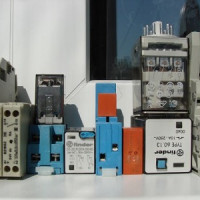 Intermediate relay: how it works, labeling and types, nuances of adjustment and connection
 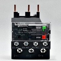 Thermal relay: operating principle, types, connection diagram + adjustment and marking
 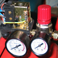 Pressure switch for compressor: device, marking + wiring diagram and adjustment
  Pulse relay for lighting control: how it works, types, labeling and connection
 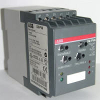 Phase control relays: operating principle, types, marking + how to adjust and connect
 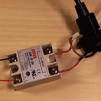 Solid State Relays: Types, Practical Applications, Wiring Diagrams
  How much does it cost to connect gas to a private house: the price of organizing gas supply
  The best washing machines with dryer: model rating and customer tips
  What is the color temperature of light and the nuances of choosing the temperature of the lamps to suit your needs
  Replacement of a geyser in an apartment: replacement paperwork + basic norms and requirements
Good afternoon. Can you tell me - what are the ways to suppress interference from relay operation?
Good afternoon, Roma. The fight against interference is a separate story that is practically not affected by the PUE.
The relay generates electromagnetic waves when closing / opening contacts. Propagating waves induce EMF in the wires, metal structures through which they pass. Let me remind you that a triggered relay starts a chain of "events" ending with the start of power equipment, starting currents, which also generate electromagnetic waves.
It is possible to protect oneself and suppress interference of this nature by concentrating the relay in separate panels, remote from devices, equipment, to which waves can harm. Shield enclosures must be grounded. Control cables, cables of operational circuits, which are threatened by interference, must have a protective sheath, braid, armor, which are grounded. Power and control cables laid in the buildings are spread.
Design organizations involved in power supply have departments that study the issues of electromagnetic compatibility of electric networks, communication networks, automation, etc.
Attached is a screenshot of the EMP items associated with the pickups and a list of GOSTs containing issues of combating interference.