Setting a call to the apartment: overview of schemes + step-by-step installation instructions

Among the electrical work, there are those that do not require a specialist call. Knowing the principles of building electrical circuits, you can independently replace the electric bell. Agree, this is a great opportunity to gain new skills and save.
But even when performing the simplest jobs with electrical installations and wires, you need to know both the basics and the small, but important nuances of installation: the choice of circuit and installation location,wire connection methods in the junction box, the electrical panel device.
We will help you to understand the stages of installation in more detail and tell you in detail how the call to the apartment is set up. And first, let's look at the types of devices and several popular schemes.
The content of the article:
Design and types of electric bells
According to the principle of operation and design features, electrical models can be divided into 2 large categories: electromechanical and electronic. They are united by the principle of operation - the sound is heard when a button is pressed. At this moment, the contacts close and voltage is applied.
The sound in electromechanical calls is heard due to the operation of the electromagnetic coil and the interaction of the shock mechanism with the electric plate. Such models do not have adjustments, and the quality and volume of sound depend on the material and dimensions of the plate, hammer and bowl.

Electronic products are distinguished by internal filling. Instead of interacting metal parts, electronics and a loudspeaker are located inside the box. The advantage is that you can adjust the sound volume, and for some models - choose a melody.
Electronic models, in turn, are divided into 2 groups:
- Wiredin which all parts are connected by wires.Pros: clear design, easy installation, reliability. Cons: depend on the supply of electricity, require drilling and gating walls.
- Wirelessgiving signals by radio waves. They work on batteries or accumulators, less often - from the network. Pluses: do not depend on connection to the power supply network, the button is protected from dust and moisture, simple installation. Cons: limited distance between the blocks, regular battery replacement.
There are still video calls with a camera, but you need to talk about their design, installation method and principle of operation separately. We will focus on current electronic models, which are present in large numbers on the domestic market.
Connection Diagram Overview
The volume of preparatory and installation work depends on the choice of the scheme. The scheme itself is selected taking into account several criteria: the type and number of devices, the need to connect to automation, the signal transmission method. Consider the most common wired options.
# 1 - Connection diagram of the old model
The connection sequence of the old model with a "bell" or "bowl" may come in handy if you started a change in wiring, but do not want to change the device itself.
The circuit is simple and clear: both network conductors, zero and phase, are directed to the 2 terminals or wires of the bell, but the phase is pre-wired into the button.

The cable serving the button and coming from the junction box is laid through a hole in the wall, most often near the front door.
Previously, the construction company was responsible for the installation of the call, and the laying of networks was originally designed. Now new houses are often rented out with imperfections, so you have to ditch the walls yourself and make holes in the wall.
Some wireless models are easier to connect - they do not need to be integrated into a common network, as the power comes from the outlet. In this case, you will have to find or install an additional outlet for a call.
Loads of the circuit are small and short-term, therefore, thin copper wires 2 * 1.5 or 3 * 1.5 can be used. Small cross-section aluminum cables are not allowed.
# 2 - One or two calls on 2 buttons
In some houses, the layout of common areas is such that a vestibule is formed for 2-3 apartments, that is, another door appears on the guest's path. So that you can call the owner of one of the apartments or any tenant, the call is installed on the door of the apartment and on the common entrance.

A scheme may also be useful in which 2 buttons are attached to two calls, and when either button is pressed, both devices work.

The phase coming from the junction box is connected by a jumper with the contacts of the buttons, and the connecting wires are sent separately - from each button to its call. For the correct application of the button is better to sign.
# 3 - Connection diagrams of modern models
Apartments in old houses were equipped with wiring using the TN-C system, now TN-S / TN-C-S is used.
Modern networks have an additional PE conductor that provides grounding. All conductors of the "ground" type connected to metal cases are connected in a junction box and grounded on the shield.

If the button is metal, it also needs grounding.
For plastic products, a simpler circuit is suitable - with 2 contacts. This is the most popular option.
But there are models with 4 terminals. They should not be confused, as they simply simplify wiring.

If there is a transformer in the kit with the call, then a different connection scheme is used.

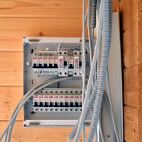
In the electrical panel, a transformer for a call is mounted, resembling a regular automatic machine in size. From it, a cable with a low voltage is sent to the distribution box.
Both wires are connected to the call: both with a low voltage, and power at 220 V, coming from the unit with a device that makes a sound.
There are other connection schemes - we advise you to take accurate information only from technical documentation and installation instructions.
Step-by-step installation instructions
The installation of the button and the indoor unit is carried out according to the instructions, which are necessarily included in the new products. We offer general instructions suitable for a standard wired model consisting of 2 main working blocks - a button and the bell itself.
Step 1 - Materials and Tools
Tools are better prepared immediately so as not to be distracted once again during operation. If you plan to ditch the walls, a wall cutter, punch or drill will come in handy. If necessary, they can be borrowed from friends or rented. Other devices and accessories are not so bulky.

A set of tools and materials for installing a call:
- construction knife;
- Screwdriver Set;
- indicator screwdriver;
- screws and a screwdriver;
- insulating tape;
- terminals.
Wire connection can be performed not only terminals - they are simply faster and more convenient. Some still use soldering, then a soldering iron is required.
We do not recommend doing twisting without soldering - this is an unreliable and dangerous way to connect the cores.

If there is no cable in the kit along with the call, you need to buy it. Before buying, look at the installation diagram and specify which cable required: 2- or 3-core.
Step 2 - preparatory work
If you are installing a wireless model, no training is needed. It is required when it is necessary to pave the way for the wires connecting the circuit elements.

The hole is usually drilled near the front door. Sometimes it is carefully masked with platbands. The wires for the button are brought out, approximately at a height of 150-160 cm from the floor, for the bell case - to the place of installation. Usually this is the area under the ceiling above the door or slightly to the side of it.
If you need to connect to the electrical panel, consider the path to the ground bus. If the bell has an adapter with a plug, select the mounting location for the case so that it looks organically on the wall.
The wires are laid in the made strobes, covered with plaster on top. To make the walls and the bell housing look neat, we recommend that you finish the walls only after the installation of the fasteners.
Step 3 - installing the ringer case
First, we connect the conductors, and then install the case on the bracket or holder. Sometimes it’s just 1-2 screws for “ears”.

We stick out the wires protruding from the wall, according to the diagram, into the housing through a special hole or unscrew the cover. Find the terminals, start veins stripped of insulationtwist.
Often in expensive or imported products, self-clamping terminals are installed, the wires in which are fixed with one click.

There are products whose body needs to be screwed to the bar. Then first we screw in the screws, and only then close the lid. As a result of proper installation, only the front decorative panel is visible, the fasteners are invisible.
Step 4 - Installing the Button
The order of installation of the button and the indoor unit does not matter, you can first connect the button, and then the case. The standard installation height is 150-160 cm, but sometimes, for objective reasons, it is fixed a little lower. It is better to retreat from the jamb 10-15 cm.

If in the kit you found a double-sided tape - it is provided for attaching the button to the wall. But it is much more reliable if it is screwed onto screws or self-tapping screws.
After installing all the elements on the dashboard, turn on the machine and check the operation of the call. If possible, adjust the volume.
Conclusions and useful video on the topic
Detailed instruction from the Russian manufacturer of cable products:
Self-installation option:
With the advent of intercoms and mobile phones, the need for a mandatory doorbell installation has disappeared. But it still remains a useful device that makes life much easier - if, for example, there is no intercom in your doorway.
Self-assembly is simple and a good training for further, more serious practices in the field of power supply of your own housing. But when working with electricity, do not forget about safety - your own and those around you.
If you are familiar with setting up a call in an apartment or house, we invite you to share your personal experience. You may have encountered installation difficulties, let's discuss them with our readers. Go to the comments, ask questions to our experts and other visitors to the site.
 Wiring in the apartment: an overview of the main schemes and the procedure for performing work
 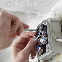 Junction box for indoor and outdoor wiring: types, classification + installation instructions
 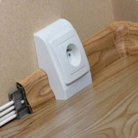 Installation of open wiring: a review of the technology of work + analysis of the main errors
 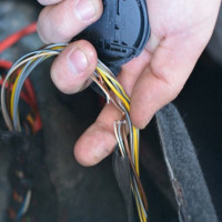 How to find a wire break in a wall: an overview of ways to detect and repair a break
 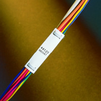 What cable to use for wiring in the apartment: a review of the wires and choosing the best option
 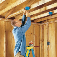 Wiring in a wooden house: design rules + step-by-step installation
  How much does it cost to connect gas to a private house: the price of organizing gas supply
  The best washing machines with dryer: model rating and customer tips
  What is the color temperature of light and the nuances of choosing the temperature of the lamps to suit your needs
  Replacement of a geyser in an apartment: replacement paperwork + basic norms and requirements