Ohm's law for the complete chain and for the section of the chain: writing formulas, description and explanation

A professional electrician, a specialist electronic engineer can’t get around Ohm’s law in his own activities, solving any problems associated with setting up, tuning, repairing electronic and electrical circuits.
Actually, everyone needs an understanding of this law. Because everyone in everyday life has to deal with electricity.
And although the law of the German physicist Ohm is provided for by a secondary school course, in practice it is not always studied in a timely manner. Therefore, we will consider in our material such a topic that is relevant for life and we will deal with the options for writing the formula.
The content of the article:
Separate section and complete electrical circuit
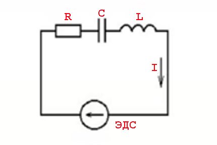
Considering the electric circuit from the point of view of applying Ohm's law to the circuit, two possible calculation options should be noted: for a single section and for a full-fledged circuit.
Calculation of the current section of the electrical circuit
The part of the circuit, as a rule, is considered part of the circuit, excluding the source of EMF, as having additional internal resistance.
Therefore, the calculation formula, in this case, looks simple:
I = U / R,
Where, respectively:
- I - current strength;
- U - applied voltage;
- R - resistance.
The interpretation of the formula is simple - the current flowing along a certain part of the circuit is proportional to the voltage applied to it, and the resistance is inversely proportional.

Thus, the formula clearly describes the dependence of the current flowing through a separate section of the electric circuit relative to certain values of voltage and resistance.
It is convenient to use the formula, for example, calculating the resistance parameters, which must be soldered into the circuit if the voltage with current is specified.

The above figure will help determine, for example, the current flowing through a 10-ohm resistance, to which a voltage of 12 volts is applied. Substituting the values, we find - I = 12/10 = 1.2 amperes.
Similarly, the tasks of finding resistance (when current with voltage are known) or voltage (when voltage with current are known) are solved.
Thus, it is always possible to select the required operating voltage, the required amperage and the optimal resistive element.

By the way, the connecting wires of any circuit are resistance. The magnitude of the load that they have to bear is determined by the voltage.
Accordingly, again using Ohm's law, it becomes possible to accurately select the necessary conductor cross-section, depending on the material of the core.
We have detailed instructions on the website cable cross section by power and current.
Calculation Option for Full Chain
A complete chain is already the site (s), as well as the source of EMF. That is, in fact, the internal resistance of the EMF source is added to the existing resistive component of the circuit section.
Therefore, some change to the above formula is logical:
I = U / (R + r)
Of course, the value of the internal resistance of the EMF in Ohm's law for a complete electric circuit can be considered negligible, although in many respects this value of resistance depends on the structure of the source of EMF.
However, when calculating complex electronic circuits, electrical circuits with many conductors, the presence of additional resistance is an important factor.

For both the circuit section and the complete circuit, the natural moment should be taken into account - the use of a constant or variable current.
If the points noted above, characteristic of Ohm's law, were considered from the point of view of using direct current, accordingly with alternating current everything looks a little different.
Consideration of the law to a variable
The concept of "resistance" to the conditions of passage of alternating current should be considered more as the concept of "impedance". This is a combination of the active resistive load (Ra) and the load formed by the reactive resistor (Rr).
Such phenomena are caused by the parameters of inductive elements and the laws of switching as applied to a variable voltage value - a sinusoidal current value.
In other words, there is an effect of advancing (lagging) current values from voltage values, which is accompanied by the appearance of active (resistive) and reactive (inductive or capacitive) capacities.
The calculation of such phenomena is carried out using the formula:
Z = U / I or Z = R + J * (XL - XC)
Where: Z - impedance; R - active load; XL , XC - inductive and capacitive load; J - coefficient.
Series and parallel connection of elements
For elements of an electric circuit (circuit section), a characteristic moment is a series or parallel connection.
Accordingly, each type of connection is accompanied by a different nature of the current flow and voltage supply. In this regard, Ohm's law also applies in different ways, depending on the option of including elements.
Resistor Circuit
In relation to a serial connection (a section of a circuit with two components), the following formula is used:
- I = i1 = I2 ;
- U = U1 + U2 ;
- R = R1 + R2
This formulation clearly demonstrates that, regardless of the number of resistive components connected in series, the current flowing in the circuit does not change.

The magnitude of the voltage applied to the active resistive components of the circuit is the sum of the total value of the emf source.
The voltage on each individual component is equal to: Ux = I * Rx.
The total resistance should be considered as the sum of the ratings of all the resistive components of the circuit.
Circuit of parallel connected resistive elements
In the case where there is a parallel connection of resistive components, the following formula is considered fair with respect to the law of the German physicist Ohm:
- I = i1 + I2 … ;
- U = U1 = U2 … ;
- 1 / R = 1 / R1 + 1 / R2 + …
Options for compiling circuit sections of a “mixed” type when parallel and serial connection are used are not ruled out.

For such options, the calculation is usually carried out by the initial calculation of the resistive rating of the parallel connection. Then, the value of the resistor connected in series is added to the result.
Integral and differential forms of law
All the above points with the calculations are applicable to conditions when conductors of a “homogeneous” structure are used in the electrical circuits.
Meanwhile, in practice, one often has to deal with the construction of a circuit where the structure of the conductors changes in different areas. For example, wires of a larger cross section or, on the contrary, smaller ones, made on the basis of different materials, are used.
To account for such differences, there is a variation of the so-called "Ohm's differential-integral law". For an infinitely small conductor, the current density level is calculated depending on the strength and conductivity.
Under the differential calculation, the formula is taken: J = ό * E
For integral calculation, respectively, the wording: I * R = φ1 - φ2 + έ
However, these examples are rather closer to the school of higher mathematics and in actual practice, a simple electrician is not actually used.
Conclusions and useful video on the topic
A detailed analysis of Ohm's law in the video below will help to finally consolidate knowledge in this direction.
A peculiar video lesson qualitatively reinforces the theoretical written presentation:
The work of an electrician or the activity of an electronic engineer is inextricably linked to moments when you really have to observe the Georg Ohm's law in action. These are some common truths that every professional should know.
Extensive knowledge on this issue is not required - it is enough to learn the three main variations of the wording to successfully apply in practice.
Do you want to supplement the above material with valuable comments or express your opinion? Please write comments in the block under the article. If you have any questions, feel free to ask our experts.
 How to calculate power, current and voltage: principles and examples of calculation for domestic conditions
  Converting Amperes to Watts: rules and practical examples of the conversion of voltage and current units
  How to convert amperes to kilowatts: principles of translation and practical examples with explanations
  Uninterrupted for the computer: rating of the best UPS
  Conventions in electrical circuits: decoding graphics and alphanumeric characters
  Convert kilowatts to horsepower: how many drugs in one kW + principles and calculation methods
  How much does it cost to connect gas to a private house: the price of organizing gas supply
  The best washing machines with dryer: model rating and customer tips
  What is the color temperature of light and the nuances of choosing the temperature of the lamps to suit your needs
  Replacement of a geyser in an apartment: replacement paperwork + basic norms and requirements