Conventions in electrical circuits: decoding graphics and alphanumeric characters

Reading electrical drawings requires certain knowledge that can be gleaned from regulatory documents. A kind of "language" of reading is the legend in electrical circuits – system of signs and symbols, mainly graphic and alphabetic. In addition to them, sometimes denominations are put in numbers.
Look, understanding the standard notation is a must for any home master. This knowledge will help you read the wiring diagram, independently draw up a wiring plan in an apartment or in a private house. We offer to understand all the intricacies of writing design documentation.
The article describes the main types of electrical circuits, as well as provides a detailed interpretation of basic images, symbols, icons and alphanumeric markers used in the preparation of drawings for the power supply device.
The content of the article:
What types of wiring diagrams can come in handy?
Consider the design information from the point of view of an amateur electrician who wants to change the wiring in the house with his own hands or draw up a drawing of connecting the cottage to electrical communications.
First you need to understand which knowledge will be useful and which will not be needed. First step – this familiarity with the species electrical circuits.

All information about the types of schemes is set out in the new edition of GOST 2.702-2011, which is called "ESKD. Rules for the implementation of electrical circuits. "
This is a duplicate of an earlier document. – GOST 2.701-2008, which just details the classification of schemes. In total, 10 species are distinguished, but in practice only one may be required. – electric.
In addition to the species classification, there is a typical one that subdivides all drawing documents into structural, general, etc., a total of 8 points.
The home master will be interested in 3 types of circuits: functional, basic, installation.
Type # 1 - Functional Diagram
The functional diagram does not contain details, it indicates the main blocks and nodes. It gives a general idea of the system. For the power supply device of a private house, it does not always make sense to draw up such drawings, since they are usually typical.
But when describing a complex electronic device or to equip an electric workshop, studio or control room, they can come in handy.

Type # 2 - circuit diagram
Schematic diagram, as opposed to functional – this is a set of conventions, without knowledge of which it is difficult to understand the structure of the network as a whole. The drawing shows all devices and the connections between them. If the circuit is complex, containing, for example, redundant circuits, then the operators use operational circuits that give an idea of the “current situation of switching devices”.
If you want to reflect only the lines of force, it is enough to draw a linear diagram, and for the image of all types of circuits with control and management devices, you need a complete one.

Type # 3 - wiring diagram
Wiring diagram – A document that is convenient to use when installing networks. From it you can find out which devices should be connected, where exactly and how far from each other they are.
The location of elements such as switches and sockets, lamps, circuit breakers. Right in the diagram you can arrange the ratings and the length of the chains.

Requirements for all types of schematic documentation are set out in GOST 2.702-2011, it is they who should be further guided in drawing up their own projects.
Here you can also find in full references to other useful documents that contain tables of graphic and letter symbols of various elements used on electrical circuits, as well as rules for their use.
Graphics in wiring diagrams
An electrical network drawing is a set of graphic elements that together form an inextricable system. In practice, this is a set of devices connected by wires.
Most notation – graphic. Letters and numbers are used to symbolically designate individual elements, their denominations and distances between objects.
Basic basic images
Electrical circuits lead to devices and installations that are equipped with contacts capable of breaking or connecting these circuits.
Simplest example – ordinary switch. All contacts are divided into closing, opening and switching – it is they that are displayed in the schemes.


The listed graphic images are mandatory when drawing up circuit diagrams and are usually understandable even to a novice electrician.
Symbols of single-line schemes
Drawings are also used to assemble electrical panels. Usually they are a single-line diagram with the designation RCD, circuit breakers, contactors and other protective equipment.
Some graphic symbols are similar to each other, therefore, when drawing up a diagram, special attention is required. For example, a contactor and a circuit breaker are denoted identically, the difference is in a small element on a fixed contact.

Special symbols indicate relay coils. – all images are based on a rectangle.

Associations or alphanumeric cues are often used to remember icons. For example, a motor drive is represented by a circle inside which is the letter "M".

When drawing up the scheme, it should be borne in mind that the quantity is also important to indicate some symbols.
For example, if you need to specify a 4-pin terminal block, you should draw four crossed out circles in a row, and not one. Paired checkmarks when displaying outlets – this is the number of wires.
How are tires and wires displayed?
For tire designations, cables and wires linear graphics are used – almost all characters consist of straight lines.
Conductor connections are indicated by dots. If there is no mark at the junction of the two lines, then this is a simple intersection.

Wires are different in appearance, purpose, load, way of laying. All this can also be displayed schematically.

Additional features facilitate the selection of materials and the installation of the mains. In the future, thanks to the characteristics indicated in the diagram, it is possible to judge the potential capabilities of the already installed electrical system.
Sockets and circuit breakers
The designation of the switches is divided into several groups – by degree of protection, installation method (hidden or open). Separately made switches in two directions. 2- and 3-key switches are designated differently.
For some light source control devices, there is no designation - for example, for button devices and dimmers.

Now to save energy in large rooms often set walk-through switchesrun from 2 or 3 points. You can also find matching icons for them.
Sockets, like switches, are divided into groups according to the degree of protection. Inside groups, devices are divided by the number of poles, the presence of protection.To indicate the blocks, alphanumeric signatures are used, indicating the number and purpose of installations in one block.

When remembering the designations of various electrical elements in the diagrams, each conditionally depicted device should be correlated with a real product.
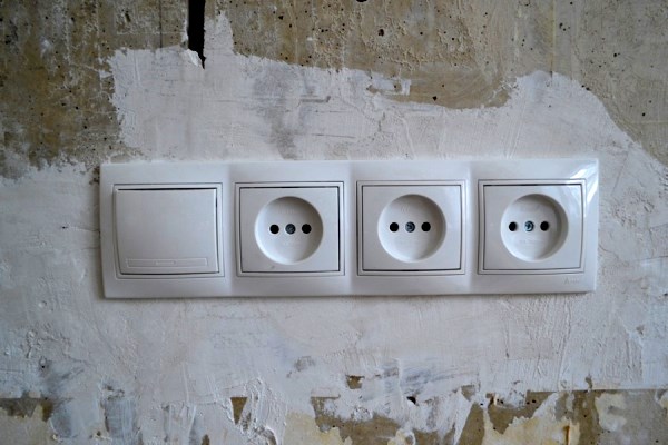
For example, popular types of outlets look like this:

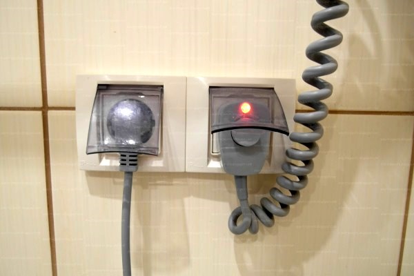
In fact, wiring devices look like this:
Switches and sockets – Some of the most “sought after” elements in circuits for home use, so they should be remembered first. Read more about the designation of such devices in the drawings and diagrams. this article.
Designation of light sources
Separate symbols are also provided for various types of lamps and luminaires. Conveniently, there are special icons for LED and fluorescent bulbs.

Standard images of various kinds of fixtures are often used for drawing up wiring diagrams.
If you use the same icons, you will have to include additional refinements, and with typical symbols you can draw a diagram much faster.
Elements for compiling circuit diagrams
The basic symbols for circuit diagrams differ little, but besides them there are also special icons to indicate all kinds of radio elements: thyristors, resistors, diodes, etc.

There are separate designations for radio devices, but when designing a home electrical network, they are usually not required.
Letter designations on wiring diagrams
To give more complete information about the device, it is signed with an abbreviated letter designation. Number of letters – 2 or 3. Sometimes the letter designation turns into an alphanumeric, if you put next to the serial number of the device.

Along with international standards, there are also Russian standards. They are listed in GOST 7624-55, but this document is declared invalid.
The article does not provide information about all the conventions. Full materials on graphic symbols can be found in GOST 2.709-89, 2.721-74, 2.755-87.
Conclusions and useful video on the topic
From drawing – to the circuit diagram:
An example of reading electrical circuits (part 1):
Continuation, or rather, part 2 on the intricacies of reading electrical device circuits (part 2):
In detail about self-charting:
Possession of information on reading and compilation of electrical circuits can be useful for installation work on the improvement of housing, and for the repair of electrical appliances. There is nothing to come up with your own symbolism when there is a professional system of symbols, which is not so difficult to learn.
Is there anything to supplement, or have questions about compiling and reading electrical circuits? You can leave comments on the publication, participate in discussions and share your own experience in the development of drawings. The contact form is located in the lower block.
 Electrical safety posters: types of plates and graphic signs + application
  Wiring diagrams in a private house: rules and design errors + nuances of electrical wiring
  Ohm's law for the complete chain and for the section of the chain: writing formulas, description and explanation
  Converting Amperes to Watts: rules and practical examples of the conversion of voltage and current units
  How to calculate power, current and voltage: principles and examples of calculation for domestic conditions
  Where to call when there is a power outage: how to find out why it was turned off and when the light will come on
  How much does it cost to connect gas to a private house: the price of organizing gas supply
  The best washing machines with dryer: model rating and customer tips
  What is the color temperature of light and the nuances of choosing the temperature of the lamps to suit your needs
  Replacement of a geyser in an apartment: replacement paperwork + basic norms and requirements
There was a thing - he was engaged in electrical installation, mainly on lighting networks. The wiring diagram gives an idea of the number of sockets, switches, fixtures and other things and their approximate location. But the way to connect them, that is, the wiring device options in the junction boxes, is already the knowledge of the electrician. And the height of the laying of the wire and the installation of devices depends on the applicable GOST.
Good afternoon, Vladimir.
In order not to disorient the readers of the article, I have to slightly correct your interpretation of the wiring diagram.
First of all, the wiring diagram sets the way to connect electricity consumers to the distribution panel.
Among the "popular" for apartment buildings is a scheme that provides for the passage of the supply line through all the rooms of the apartment with the subsequent arrangement of junction boxes, from which lamps, sockets, etc. are powered.
The “star” power supply scheme is fundamentally different and practically not applied - separate current collectors are connected from the switchboard through the machines.
The next option is a mixed scheme: all consumers are divided into categories and they are fed from the shield by separate protected lines, from which branches go through the distribution boxes.
There may be other options offered to the project customer by the contractor-developer of the power supply scheme. That is, the work of an electrician is your fantasy.