Converting Amperes to Watts: rules and practical examples of the conversion of voltage and current units

Owners of private houses, apartments, cottages or small utility rooms connected to electricity often need to convert amperes to watts or solve the inverse problem. To carry out transfers of units that determine the characteristics of the current, well-known formulas are used, which are based on Ohm's law.
We will talk about how to correctly translate physical units. In addition, the article we presented provides methods for determining the operating power and starting currents of home appliances. The nuances of calculating the cross section of the components of the wiring are analyzed.
The content of the article:
Determining the power of connected devices
In order to calculate the value of the maximum possible power on a circuit section, it is necessary to summarize the performance of all connected devices. But not everything is so simple: many of these devices are complex electrodynamic systems, so you need to correctly determine their parameters.
Active and full power components
Active (or consumed) power of the device (P) determines the irrevocable loss of electricity during its operation. It is this indicator that the electric meter will calculate, and, therefore, it affects the amount of resources (money) spent during the operation of the device.
The active component in watts is indicated for all consumers of electricity. However, there is another indicator - power factor (cos (f)), which can be found in the technical documentation, as well as on special plates or labels with the main parameters.
Through it, you can calculate the total power (S) devices according to the following formula:
S = P / cos (f)
The physical meaning of these quantities can be described as follows: current with full power goes from the source (transformer) to the electrical appliance, which converts its active component, and returns the remaining (reactive) back to the network. Thus, the load on the circuit components (wiring and circuit breakers) must be calculated precisely taking into account the full power.

For most household appliances, the coefficient is unity, therefore, the active and full power are the same. But if the consumer has capacitors (capacities) or an inductor, a reactive component occurs.
You need to pay attention to the following types of equipment:
- refrigerators;
- washing machines;
- air conditioners;
- Pumps
- induction furnaces and stoves;
- fluorescent lights;
- TV sets
- computers and other equipment with electronic filling.
Also often to electrical system of private houses or economic facilities connect machine tools with electric motors, arc welding machines and other equipment, whose total power is significantly higher than consumed. Therefore, you need to carefully familiarize yourself with the technical characteristics of the devices before connecting them to the network.
Inrush currents of compressors and motors
If the household appliances are equipped with an electric motor, compressor, incandescent filament or a transformer at the entrance to the power supply, then at the beginning of its operation, starting currents occur for a short time (IP) Their value can several times exceed the nominal values (In) specified in the device passport.
These values are related by the following formula:
IP = k * In
Here k - coefficient of multiplicity of starting current.

The multiplicity index exceeds the value “2” in the following common household appliances:
- submersible pump;
- fridge and freezer;
- powerful vacuum cleaner;
- Washer;
- split system;
- microwave;
- neon lighting;
- some types of power tools (drill, perforator, compressor).
The calculation of the total power in the presence of such devices in the circuit must be carried out taking into account their starting currents. Since the time of increased power consumption is small, and synchronous inclusion is unlikely, it is enough to take one, the most powerful device with respect to starting currents.
Amperage and wiring parameters
To determine the required cross-section of conductors and circuit breakers translate the total number of watts into amperes and obtain the value of the maximum continuous current.
The correlation of the cross-section of the conductors and the maximum current strength acceptable for wiring is performed using tables provided by cable manufacturers. Depending on the manufacturer, the main indicators may vary slightly, but at the same time they must always comply with current GOST 31996-2012.

Sometimes they choose a wiring not with a minimum acceptable cross-section, but with a slightly larger one. This is justified, since the reserve bandwidth allows you to connect new electrical appliances without expensive dismantling of old and laying new cables.
Parameters set to the electrical panel circuit breakers they are selected so that it is guaranteed to operate on shutdown if the current strength exceeds a value determined as the maximum allowable for the laid wiring.
Rated current of the machine (In) are calculated by the current acceptable for the cable (Ip) according to the following formula:
In <= Ip / 1.45
Usually, an automatic machine with the maximum value among the permitted nominal values is chosen in order to minimize the likelihood of disconnection with a strong, but still permissible load on the circuit.
The relationship of basic electrical quantities
Power and amperage can be connected through voltage (U) or circuit resistance (R) However, in practice, apply the formula P = I2 * R is difficult, since it is difficult to accurately calculate the resistance in a real area.
Single and three phase connection
Most electrical wiring for household use is single-phase.
In this case, the conversion of the total power (S) and AC power (I) using a known voltage occurs according to the following formulas arising from Ohm's classical law:
S = U * I
I = S / U
Now the practice of bringing a three-phase network to residential, domestic and small industrial facilities has become widespread. This is justified from the position of minimizing the costs of cables and transformers, which are borne by the company supplying electricity.

The cross-section of the wiring conductors and the rated power when using three-phase consumers is also determined by the current strength, which is calculated as follows:
Il = S / (1.73 * Ul)
Here is the index “l”Means the linear nature of the quantities.
In the planning and subsequent implementation indoor wiring it is better to isolate three-phase consumers in separate circuits. Devices operating from standard 220 V, try to more or less uniformly disperse in phases, so that there is no significant distortion in power.
Sometimes they allow mixed connection of devices operating both from one and from three phases. This situation is not the simplest, so it is better to consider it with a specific example.
Let a three-phase induction furnace with an active power of 7.0 kW and a power factor of 0.9 be included in the circuit. A microwave oven of 0.8 kW is connected to phase “A” with a coefficient “2” of the multiplicity of inrush current, and to phase “B” - an electric kettle of 2.2 kW. It is necessary to calculate the power supply parameters for this section.

We determine the total power of all devices:
Si = Pi / cos (f) = 7000 / 0.9 = 7800 V * A;
Sm = Pm * 2 = 800 * 2 = 1600 V * A;
Swith = Pc = 2200 V * A.
Determine the current strength of each device:
Ii = Si / (1.73 * Ul) = 7800 / (1.73 * 380) = 11.9 A;
Im = Sm / Uf = 1600/220 = 7.2 A;
Ic = Sc / Uf = 2200/220 = 10 A.
We determine the current strength in phases:
IAND = Ii + Im = 11.9 + 7.2 = 19.1 A;
IB = Ii + Ic = 11.9 + 10 = 21.9 A;
IWITH = Ii = 11.9 A.
The maximum current with all the electrical appliances turned on flows through phase “B” and will be equal to 21.9 A. A sufficient combination for the hassle-free operation of all devices in this circuit is a 4.0 mm section of copper conductors2 and circuit breaker on 20 or 25 A.
Typical household voltage
Since power and current strength are connected through voltage, it is necessary to precisely determine this value. Before the introduction of GOST 29322-2014 from October 2015, the value for an ordinary network was 220 V, and for a three-phase network it was 380 V.
According to a new document, these indicators are brought into line with European requirements - 230/400 V, but most household power supply systems are still functioning according to the old parameters.

Deviation of 5% of the real value from the reference value is acceptable for any period, and 10% - no more than one hour. When lowering voltage, some consumers, such as an electric kettle, incandescent lamp or microwave, lose in power.
But if the device is equipped with an integrated stabilizer (for example, a gas boiler) or has a separate switching power supply, then the power consumption will remain constant.
In this case, given that I = S / U, a voltage drop will increase the current strength. Therefore, it is not recommended to select the cross-section of the cable conductors “end to end” to the maximum design values, but it is desirable to have a margin of 15-20%.
Useful video on the topic
Measurement of current with a multimeter and subsequent calculation of power:
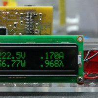
Electronic device for determining voltage, current and automatic power calculation:
Determining the current strength, knowing the network voltage and the total power of the devices in the circuit, is quite simple. The difficulty lies in measuring or calculating the initial parameters.
If there are doubts about the correctness of the solution found, it is better to turn to electricians, since errors in the calculations can lead to serious problems.
Want to share your own experience in converting amperes to watts? Is there an original method in your arsenal that can be useful to site visitors? Please write comments in the block below, post a photo and ask questions about the topic of the article.
 How to convert amperes to kilowatts: principles of translation and practical examples with explanations
  Convert kilowatts to horsepower: how many drugs in one kW + principles and calculation methods
  How to calculate power, current and voltage: principles and examples of calculation for domestic conditions
 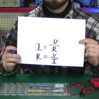 Ohm's law for the complete chain and for the section of the chain: writing formulas, description and explanation
  Wiring diagrams in a private house: rules and design errors + nuances of electrical wiring
  Uninterrupted for the computer: rating of the best UPS
  How much does it cost to connect gas to a private house: the price of organizing gas supply
  The best washing machines with dryer: model rating and customer tips
  What is the color temperature of light and the nuances of choosing the temperature of the lamps to suit your needs
  Replacement of a geyser in an apartment: replacement paperwork + basic norms and requirements
I myself work as an adjustment engineer, but only in underground electrical installations. Often you have to calculate the settings and other parameters. Sometimes on the power supply schemes simply indicate the value of the short-circuit current And here it is very difficult to understand, it’s two or three phase current. Therefore, you yourself have to recount everything and make logical conclusions.
Good afternoon, Vladimir.
Usually the number of phases in the circuits, for example, the distribution network is indicated by dashes - attached a screenshot. Currents calculated for the most severe cases of faults. For a three-phase network, this is a metal three-phase circuit, similarly for two, single-phase. A person applying to the scheme I to. C., already knows which option he considered. As the types of c. look at the second screenshot. Teach your colleagues order.