Solar charge controller: circuit, principle of operation, connection methods

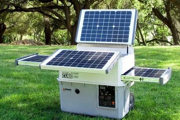
Solar energy is so far limited (at the household level) to the creation of photovoltaic panels of relatively low power. But regardless of the design of the photoelectric converter of the light of the sun into current, this device is equipped with a module called the solar charge controller.
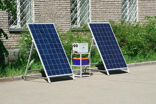
Indeed, a solar battery photosynthesis installation scheme includes a storage battery - a storage device for energy received from a solar panel. It is this secondary energy source that is served primarily by the controller.
In the article we present, we will understand the device and the principles of operation of this device, and also consider how to connect it.
The content of the article:
Solar controllers
The electronic module, called the controller for the solar battery, is designed to perform a number of control functions during the charge / discharge process solar battery.
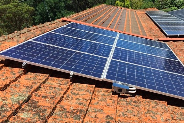
When sunlight falls on the surface of a solar panel installed, for example, on the roof of a house, this light is converted into electric current by the photocells of the device.
The energy received, in fact, could be supplied directly to the storage battery. However, the process of charging / discharging a battery has its own subtleties (certain levels of currents and voltages). If you neglect these subtleties, the battery for a short period of operation will simply fail.
In order not to have such sad consequences, a module called a charge controller for the solar battery is designed.
In addition to monitoring the battery level, the module also monitors energy consumption. Depending on the degree of discharge, the circuit of the battery charge controller from the solar battery regulates and sets the current level necessary for the initial and subsequent charge.

In general, in simple terms, the module provides a carefree "life" for the battery, which periodically accumulates and gives energy to consumer devices.
Practical Types
At the industrial level, two types of electronic devices have been launched and are being manufactured, the execution of which is suitable for installation in the solar energy system circuit:
- PWM series devices.
- MPPT series devices.
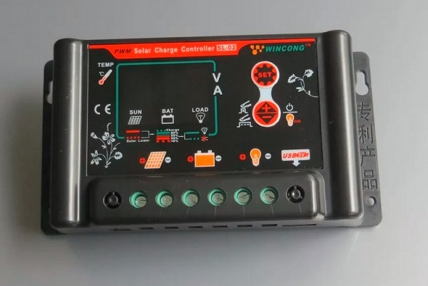
The first type of controller for a solar battery can be called an "old man." Such schemes were developed and put into operation at the dawn of the formation of solar and wind energy.
The principle of operation of the PWM controller circuit is based on pulse width modulation algorithms. The functionality of such devices is somewhat inferior to the more advanced MPPT series devices, but in general they also work quite efficiently.

Designs using the Maximum Power Point Tracking technology (tracking the maximum power limit) are distinguished by a modern approach to circuitry solutions and provide more functionality.
But if you compare both types of controller and, especially, with a bias towards the domestic sphere, MPPT devices do not look in the bright light in which they are traditionally advertised.
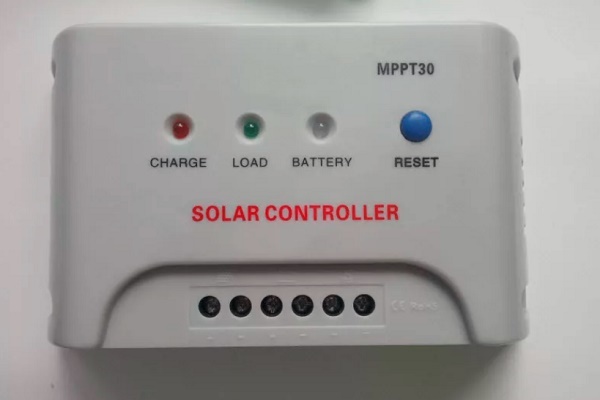
MPPT type controller:
- has a higher cost;
- has a sophisticated tuning algorithm;
- gives power gain only on panels of a significant area.
This type of equipment is more suitable for global solar energy systems.

It is more profitable to buy and operate the PWM controller (PWM) with the same effect for the needs of an ordinary user from a household environment, which usually has small-area panels.
Block diagrams of controllers
Schematic diagrams of the PWM and MPPT controllers for consideration by their narrow-minded look - this is too complicated a moment, coupled with a subtle understanding of electronics. Therefore, it is logical to consider only structural schemes. This approach is understandable to a wide range of individuals.
Option # 1 - PWM devices
The voltage from the solar panel through two conductors (plus and minus) comes to the stabilizing element and the dividing resistive chain. Due to this piece of the circuit, potential equalization of the input voltage is obtained and, to some extent, they organize the protection of the controller input from exceeding the input voltage boundary.
It should be emphasized here: each individual model of the device has a specific boundary for the input voltage (indicated in the documentation).

Further, the voltage and current are limited to the required value by power transistors. These circuit components, in turn, are controlled by the controller chip through the driver chip. As a result, the output voltage of the pair of power transistors sets the normal value of voltage and current for the battery.
Also in the circuit there is a temperature sensor and a driver that controls the power transistor, which regulates the load power (protection against deep discharge of the battery). The temperature sensor monitors the heating status of important elements of the PWM controller.
Usually the temperature level inside the case or on the radiators of power transistors. If the temperature goes beyond the limits set in the settings, the device disconnects all active power lines.
Option # 2 - MPPT Instruments
The complexity of the scheme in this case is due to its addition to a number of elements that build the necessary control algorithm more carefully, based on working conditions.
Voltage and current levels are monitored and compared by comparator circuits, and the maximum output power is determined from the results of the comparison.

The main difference between this type of controllers and PWM devices is that they are able to adjust the energy solar module to maximum power, regardless of weather conditions.
The circuit of such devices implements several control methods:
- disturbances and observations;
- increasing conductivity;
- current sweep;
- constant voltage.
And in the final segment of the general action, an algorithm for comparing all these methods is also used.
Ways to connect controllers
Considering the topic of connections, it should immediately be noted: to install each individual device, a characteristic feature is the work with a specific series of solar panels.
So, for example, if a controller is used that is designed for a maximum input voltage of 100 volts, a series of solar panels should output no more than this value at the output.

Before connecting the device, it is necessary to determine the place of its physical installation. According to the rules, dry, well-ventilated rooms should be chosen as the installation site. The presence of flammable materials near the device is excluded.
The presence of sources of vibration, heat and humidity in the immediate vicinity of the device is unacceptable. The installation site must be protected from precipitation and direct sunlight.
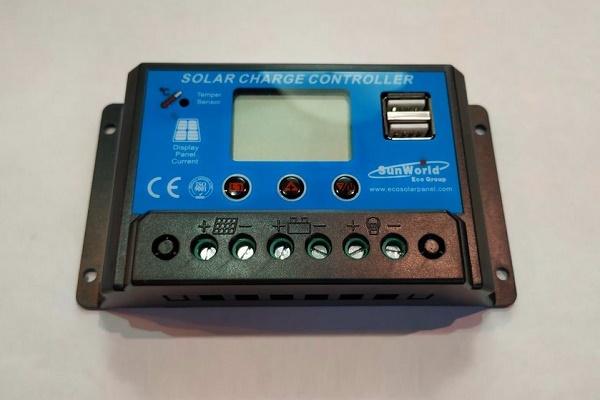
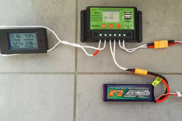
PWM Model Connection Technique
Almost all manufacturers of PWM-controllers require to follow the exact sequence of connecting devices.
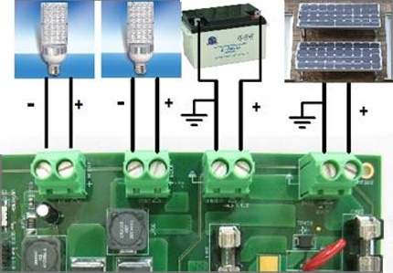
Peripheral devices must be connected in full accordance with the designations of the contact terminals:
- Connect the battery wires at the terminals of the battery device in accordance with the indicated polarity.
- At the contact point of the positive wire, switch on the protective fuse.
- On the controller contacts intended for the solar panel, fix the conductors coming from the solar panel panels. Observe polarity.
- Connect a test lamp of the corresponding voltage (usually 12 / 24V) to the terminals of the load of the device.
The specified sequence must not be violated. For example, it is strictly forbidden to connect solar panels in the first place with an unconnected battery. By such actions, the user risks “burning” the device. AT this stuff the assembly diagram of solar panels with a battery is described in more detail.
Also for PWM series controllers, it is not permissible to connect a voltage inverter to the controller's load terminals. The inverter should be connected directly to the battery terminals.
Procedure for connecting MPPT devices
General requirements for physical installation for this type of apparatus do not differ from previous systems. But the technological installation is often somewhat different, since MPPT controllers are often considered more powerful devices.

For example, for powerful systems, these requirements are supplemented by the fact that manufacturers recommend taking a cable for power connection lines, designed for a current density of at least 4 A / mm2. That is, for example, for a controller for a current of 60 A, you need a cable to connect to the battery with a cross section of at least 20 mm2.
Connecting cables must be equipped with copper lugs, tightly crimped with a special tool. The negative terminals of the solar panel and battery must be equipped with adapters with fuses and switches.
This approach eliminates energy losses and ensures the safe operation of the installation.

Before connecting solar panels to the device, make sure that the voltage at the terminals matches or is less than the voltage that is permissible to apply to the input of the controller.
Connecting peripherals to the MTTP device:
- Switch panel and battery switches to the “off” position.
- Remove the protective fuses on the panel and battery.
- Connect the battery terminals to the controller terminals for the battery cable.
- Connect the cable to the terminals of the solar panel with the controller terminals marked with the corresponding sign.
- Connect the ground terminal to the ground bus with a cable.
- Install the temperature sensor on the controller according to the instructions.
After these steps, it is necessary to replace the previously removed battery fuse and put the switch in the “on” position. A battery detection signal will appear on the controller screen.
Then, after a short pause (1-2 minutes), put the previously removed fuse of the solar panel into place and put the panel switch in the “on” position.
The instrument screen will show the voltage value of the solar panel. This moment indicates the successful launch of a solar power plant in operation.
Conclusions and useful video on the topic
The industry produces multifaceted devices in terms of circuit solutions. Therefore, it is impossible to give unambiguous recommendations regarding the connection of all installations without exception.
However, the main principle for all types of devices remains the same: without connecting the battery to the controller buses, connection to photovoltaic panels is unacceptable. Similar requirements apply for inclusion in the scheme. voltage inverter. It should be considered as a separate module connected to the battery by direct contact.
If you have the necessary experience or knowledge, please share it with our readers. Leave your comments in the box below. Here you can ask a question about the topic of the article.
 The principle of operation of the solar battery: how the solar panel is arranged and works
 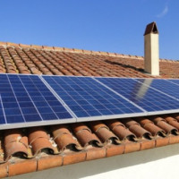 Schemes and methods of connecting solar panels: how to properly install the solar panel
  Solar panels for summer cottages and houses: types, principle of operation and calculation procedure for solar systems
  Connection diagram for solar panels: to the controller, to the battery and to the serviced systems
  How to make a solar battery with your own hands: methods of assembly and installation of a solar panel
 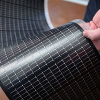 Flexible solar panels: an overview of typical designs, their characteristics and connection features
  How much does it cost to connect gas to a private house: the price of organizing gas supply
  The best washing machines with dryer: model rating and customer tips
  What is the color temperature of light and the nuances of choosing the temperature of the lamps to suit your needs
  Replacement of a geyser in an apartment: replacement paperwork + basic norms and requirements
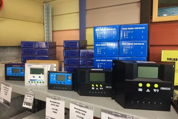
Initially, when installing solar panels to power our small cottage, a PWM controller was used. However, after five years of operation, it failed. Subsequently, on the recommendation of the wizard, I purchased an MPPT type controller, which was successfully mounted in the circuit. After six months of impeccable work, he sparkled, and his screen went blank. I again called the wizard and replaced the block.
Now I'm worried, but was it worth it to change the proven PWM controller to the new-fangled MPPT? What is the reason for such a short-lived MPPT block?
Firstly, the PWM controller has a simpler structure, respectively, this device has fewer elements that can fail. But the MPPT controller makes it possible to increase the charging current that is supplied to the batteries from solar panels, up to 30%, when compared with conventional PWM controllers! So it makes sense to use more modern MPPT controllers.
Secondly, did you find out the cause of the breakdown? I think that here is one of two things: either a manufacturing defect, or an error in the installation process, which led to a breakdown as a result.
Please write the reason for the failure of the new MPPT controller. Did you use the warranty service? Just in my memory, even the most budget models did not fail earlier than after three years of operation.
Hello! I wanted to put solar panels. Consumption email. house energy 4 kWh / day. I calculated the battery capacity, I got about 450 A. To charge such a volume, 45 A is required. To give so much current, the power of the panel should be 1750 W (in this U = 38.9 V).
It turns out that not all controllers can receive current with such power. I'm actually not special on this topic, there is no one to consult with. Can you tell me something?